


22-11
Cisco IOS Software Configuration Guide for Cisco Aironet Access Points
OL-11350-01
Chapter 22 Wireless Device Troubleshooting
Checking the Top Panel Indicators
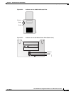
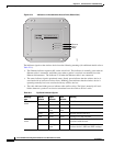
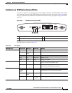
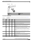
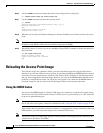
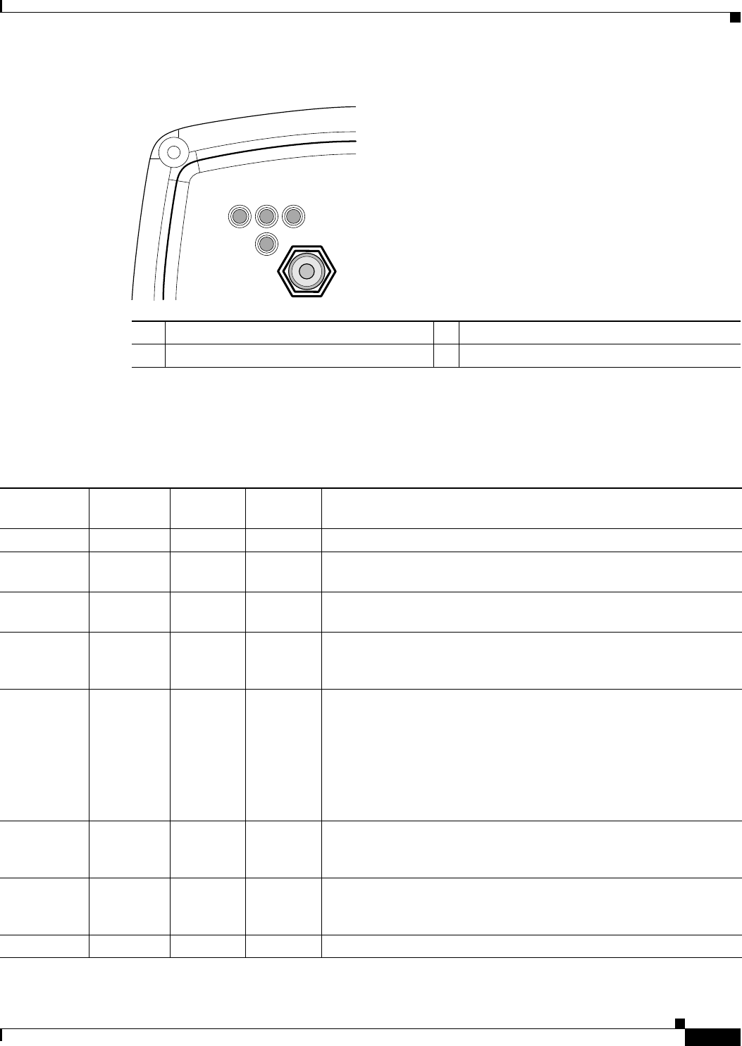
Figure 22-7 LEDs
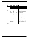
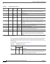
Normal Mode LED Indications
During access point/bridge operation the LEDs provide status information as shown in Table 22-4.
R Radio LED E Ethernet LED
S Status LED I Install LED
117061
RS
I
E
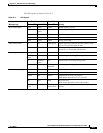
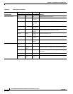
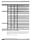
Table 22-4 LED Indications
Ethernet
LED
Status
LED
Radio
LED
Install
LED
Meaning
Off — — — Ethernet link is down or disabled.
Blinking
green
— — — Transmitting and receiving Ethernet packets.
Blinking
amber
— — — Transmitting and receiving Ethernet errors.
amber — — — Firmware error—disconnect and reconnect the power injector power
jack. If the problem continues, contact technical support for
assistance.
— Blinking
green
— — Root bridge mode—no remote bridges are associated.
Non-root bridge mode—not associated to the root bridge.
If all bridges are powered up, this could be caused by incorrect SSID
and security settings or improper antenna alignment. You should
check the SSID and security settings of all bridges and verify antenna
alignment.
If the problem continues, contact technical support for assistance.
— Green — — Root mode—associated to at least one remote bridge.
Non-root mode—associated to the root bridge.
This is normal operation.
— Blinking
amber
— — General warning—disconnect and reconnect the power injector power
jack. If the problem continues, contact technical support for
assistance.
— Amber — — Loading firmware.