


22-13
Cisco IOS Software Configuration Guide for Cisco Aironet Access Points
OL-11350-01
Chapter 22 Wireless Device Troubleshooting
Checking the Top Panel Indicators
Power Injector
When the power injector is powered up, it applies 48-VDC to the dual-coax cables to the access
point/bridge.
When power is applied to the access point/bridge, the unit activates the bootloader and begins the POST
operations. The access point/bridge begins to load the IOS image when the Post operations are
successfully completed. Upon successfully loading the IOS image, the unit initializes and tests the radio.
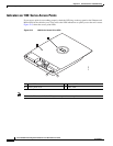
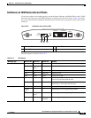
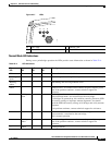
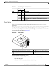
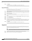
The power injector LED is shown in Figure 22-8.
Figure 22-8 Power Injector
The power injector is available in two models:
• Cisco Aironet Power Injector LR2—standard version (included with the bridge)
–
48-VDC input power
–
Uses the 48-VDC power module (included with the bridge)
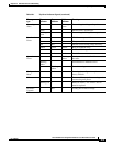
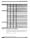
Radio 1 2 Radio not detected—contact technical support for assistance.
1 3 Radio not ready—contact technical support for assistance.
1 4 Radio did not start—contact technical support for assistance.
1 5 Radio failure—contact technical support for assistance.
1 6 Radio did not flash its firmware—contact technical support for
assistance.
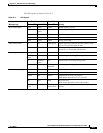
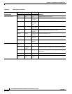
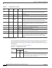
Table 22-5 LED Blinking Error Codes (continued)
LED
Blinking Codes
Description
First
Digit
Second
Digit
1 Dual-coax Ethernet ports (F-Type connectors) 4 Ethernet LAN port (RJ-45 connector)
2 Power LED 5 Console serial port (RJ-45 connector)
3 Power jack
117189
CISCO AIRONET
POWER INJECTOR
54
11
3
2