


22-14
Cisco IOS Software Configuration Guide for Cisco Aironet Access Points
OL-11350-01
Chapter 22 Wireless Device Troubleshooting
Checking Power
• Cisco Aironet Power Injector LR2T—optional transportation version
–
12- to 40-VDC input power
–
Uses 12 to 40 VDC from a vehicle battery
Checking Power
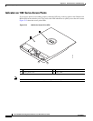
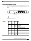
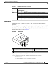
You can verify the availability of power to the access point/bridge by checking the power injector LED
(see Figure 22-8):
• Power LED
–
Green color indicates input power is being supplied to the bridge.
–
Red color indicates an overcurrent or overvoltage error condition—disconnect input power from
the power injector, check all coax cable connections for a possible short, wait approximately 1
minute, and reconnect input power to the power injector. If the LED turns red again, contact
technical support for assistance.
Note The power injector requires approximately 50 seconds to recover from an overcurrent or
overvoltage condition.
Off indicates input power is not available—verify that the power module is connected to the power
injector and that AC power is available or that 12- to 40-VDC input power is connected to the power
injector.
Low Power Condition
Access points can be powered from the 48-VDC power module or from an in-line power source. The
1130 and 1240 access points support the IEEE 802.3af power standard, Cisco Pre-Standard PoE
protocol, and Cisco Intelligent Power Management for in-line power sources.
For full operation, the 1130 and 1240 series access points require 12.95 W of power. The power module
and Cisco Aironet power injectors are capable of supplying the required power for full operation, but
some inline power sources are not capable of supplying 12.95 W. Also, some high-power inline power
sources, might not be able to provide 12.95 W of power to all ports at the same time.
Note An 802.3af compliant switch (Cisco or non-Cisco) is capable of supplying sufficient power for full
operation.
On power up, the 1130 and 1240 series access points are placed into low power mode (both radios are
disabled), Cisco IOS software loads and runs, and power negotiation determines if sufficient power is
available. If there is sufficient power then the radios are turned on; otherwise, the access point remains
in low power mode with the radios disabled to prevent a possible over-current condition. In low power
mode, the access point activates the Status LED low power error indication, displays a low power
message on the browser and serial interfaces, and creates an event log entry.