


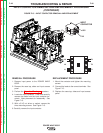
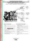
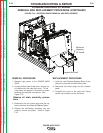
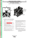
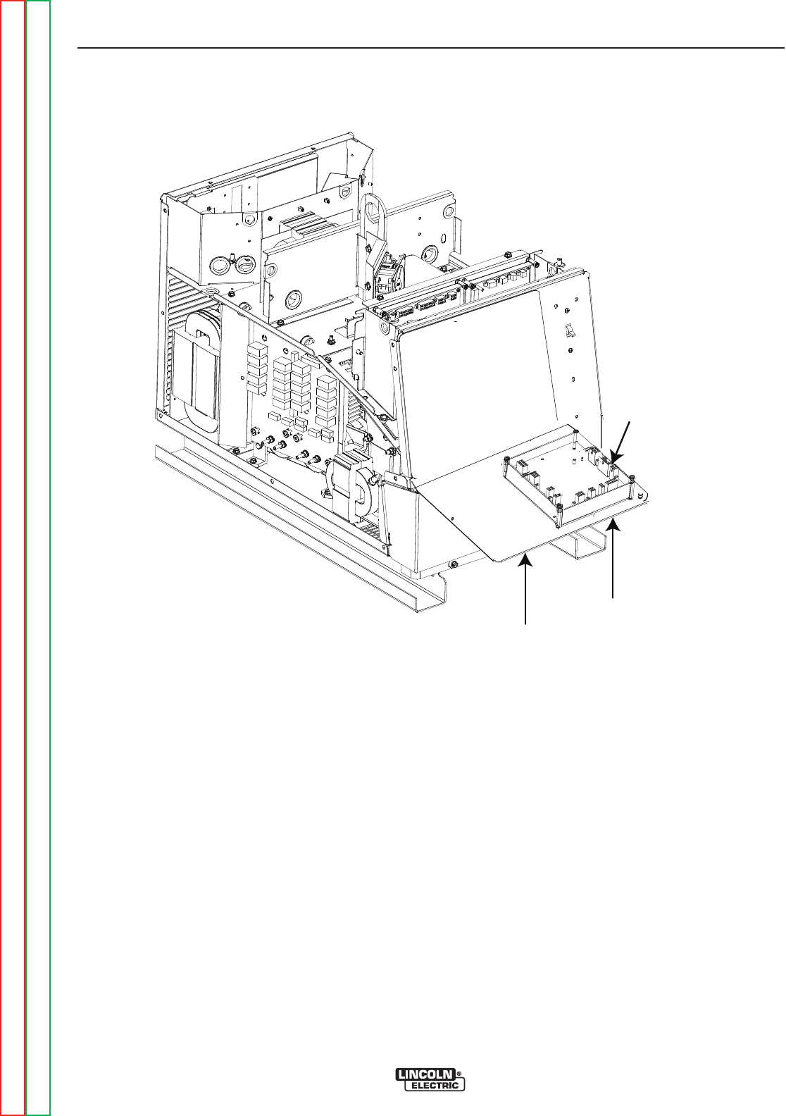
Support the Panel
Ethernet/
Gateway
PC Board
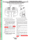
FIGURE F.19 – GATEWAY BOARD REMOVAL AND REPLACEMENT
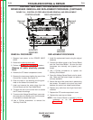
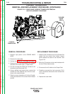
ETHERNET/GATEWAY PC BOARD
REMOVAL AND REPLACEMENT PROCEDURE (CONTINUED)
REMOVAL PROCEDURE
1. Remove input power to the POWER WAVE
655/R.
2. Using a phillips head screw driver, remove the
six screws from the case front cover. Tilt the
cover down and support it from below to avoid
stressing the electrical connections. See
Figure F.19.
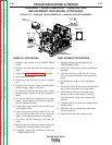
Observe all static electricity precau-
tions
.
3. Disconnect the four molex plugs and the net-
work cable from the Ethernet/Gateway Board.
4. Remove the self-locking mounting nuts and
carefully remove the board. Refer to Figure
F.19.
REPLACEMENT PROCEDURE
1. Install the new Ethernet/Gateway Board to the
case front cover with the self-locking nuts.
2. Reconnect the molex plugs and the network
cable.
3. Re-attach the cover to the case front, being
careful not to stress or pinch the wires.
TROUBLESHOOTING & REPAIR
F-56 F-56
POWER WAVE 655/R
Return to Section TOC Return to Section TOC Return to Section TOC Return to Section TOC
Return to Master TOC Return to Master TOC Return to Master TOC Return to Master TOC