


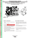
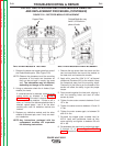
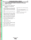

FIGURE F.22 – RECTIFIER MODULE REPLACEMENT
OUTPUT RECTIFIER AND RECTIFIER MODULE REMOVAL
AND REPLACEMENT PROCEDURE (CONTINUED)
RECTIFIER MODULE TESTING
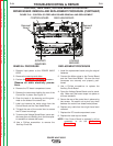
1. Remove the leads and copper plate from one of
the Diode Module pairs. (See Figure F.22).
NOTE: Observe the placement and the mounting
sequence of the leads and hardware so
they can be put back in exactly the same
way. The assemblies may be different,
depending on the age of the machine.
2. Using an ohmmeter check the 4 diodes (2 per
module) for shorts.
If a shorted device is detected, recheck at the
output studs as directed in the Output
Rectifier test. If the short is cleared there are
no more defective modules. If there is still a
short, or if none of the disconnected devices is
shorted, repeat steps 1 and 2 for the other
module pairs untill all defective devices are
located.
3. Replace any defective module and the other
module of the same pair, even if only one mod-
ule is defective.
NOTE: Any instructions packaged with the
replacement modules will supersede
the following instructions.
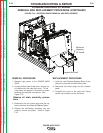
RECTIFIER MODULE REPLACEMENT
1. Remove the cap screw from the center and the
two hex-head bolts that mount the module to
the heat sink, and remove the module.
2. Apply a thin, even film (.004” t0 .01”) of thermal
compound (Penetrox A13) to the module. Keep
the compound away from the mounting holes.
Compound in the holes or on the threads of the
screws will affect the ability to get the proper
torque.
3. Press module against the heat sink, aligning it
with the mounting holes and start all three
screws by hand.
4. Tighten the two outer screws to between 5 and
10 in.-lbs
5. Tighten the center screw to between 12 and 18
in.-lbs.
6. Tighten the outer screws again, to between 30
and 40 in.-lbs.
7. Re-install the copper plate, snubber lead (or
M.O.V. lead) and transformer leads as they
were originally and tighten to between 30 and
40 in.-lbs.
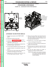
8. Re-assemble the machine by performing steps
2 through 13 of Accessing the Rectifier
Module procedure in reverse order.
TROUBLESHOOTING & REPAIR
F-61 F-61
POWER WAVE 655/R
Return to Section TOC Return to Section TOC Return to Section TOC Return to Section TOC
Return to Master TOC Return to Master TOC Return to Master TOC Return to Master TOC
Copper Plate
Original Modules may
have 1/4-20 bolts in
place of studs