


INPUT
CONTACTOR
601
X4
POWER BOARD
RECTIFIER BRIDGE
X1
X2
+
-
X3
X5
AUXILIARY
TRANSFORMER #1
WHITE RED
FAN MOTOR
WINDING
FAN RELAY
444
X3A
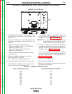
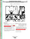
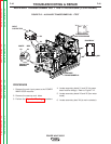
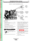
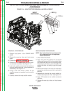
FIGURE F.12 – AUXILIARY TRANSFORMER NO. 1 TEST
AUXILIARY TRANSFORMER NO. 1 TEST PROCEDURE (CONTINUED)
PROCEDURE
1. Remove the main input power to the POWER
WAVE 655/R machine.
2. Remove the case top and sides.
3. Perform the Capacitor Discharge procedure.
4. Locate secondary leads X1 and X2 (at power
board rectifier bridge). Refer to Figure F.12.
5. Locate secondary leads X3 and X5 (fan motor
leads).
6. Locate secondary lead X4 (at main contactor).
TROUBLESHOOTING & REPAIR
F-40 F-40
POWER WAVE 655/R
Return to Section TOC Return to Section TOC Return to Section TOC Return to Section TOC
Return to Master TOC Return to Master TOC Return to Master TOC Return to Master TOC