


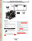
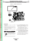
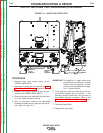


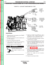
NEGATIVE (-)
OUTPUT
TERMINALS
POSITIVE (+)
OUTPUT
TERMINALS
R1
FIGURE F.11 – OUTPUT RECTIFIER TEST
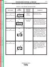
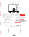
OUTPUT RECTIFIER TEST PROCEDURE (CONTINUED)
PROCEDURE
1. Remove main input supply power to the
POWER WAVE 655/R.
2. Remove the case sides and perform the Input
Filter Capacitor Discharge procedure.
3. Remove any output cables that may be con-
nected to the POWER WAVE 655/R.
4. Disconnect one end of lead 206A that connects
R1 to the Positive Output Terminal.
5. With an ohmmeter, measure the resistance
between the positive and negative output termi-
nals. Refer to Figure F.11.
IMPORTANT: The positive (+) meter probe must
be attached to the positive (+) output
terminal and the negative (-) meter
probe must be attached to the nega-
tive (-) output terminal.
6. If the reading is more than 200 ohms, the out-
put rectifier modules are not shorted. If the
reading is less than 200 ohms, one (or more) of
the rectifier modules is shorted. Refer to the
Output Rectifier Module Replacement proce-
dure.
7. Reconnect lead 206A.
8. Replace the case sides.
TROUBLESHOOTING & REPAIR
F-38 F-38
POWER WAVE 655/R
Return to Section TOC Return to Section TOC Return to Section TOC Return to Section TOC
Return to Master TOC Return to Master TOC Return to Master TOC Return to Master TOC