


1
2
5
3
4
3
2
1
5
2
6
3
6
4
4
1
350
(WHITE)
352
(BLACK)
33
(RED)
32
(WHITE)
352A
(BLACK)
H6
33A
(RED)
H1
To WATER
COOLER
RECEPTACLE
(S8)
To S4, CB2
& AUX. FAN
To AUX.ILIARY
TRANSFORMER
#2 PRIMARY
(P50)
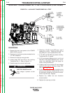
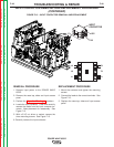
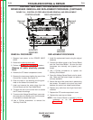
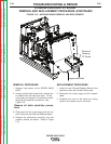
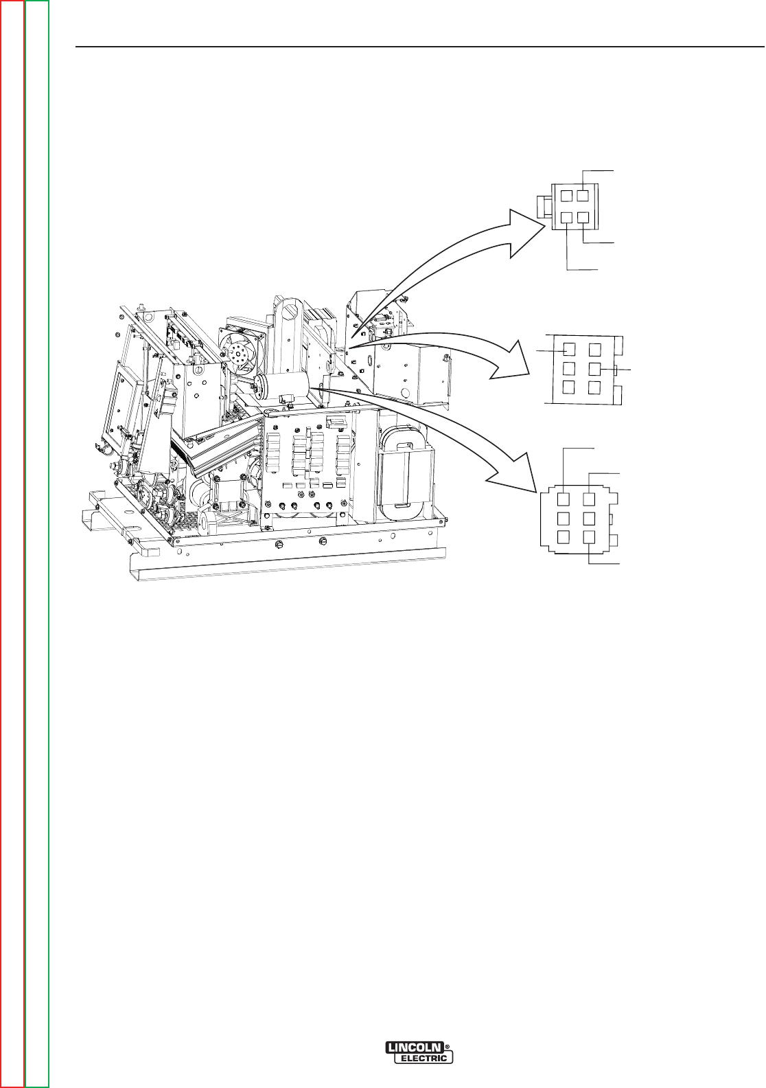
FIGURE F.17 – AUXILIARY TRANSFORMER NO. 2 REMOVAL AND REPLACEMENT
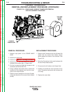
AUXILIARY TRANSFORMER NO. 2 REMOVAL AND
REPLACEMENT PROCEDURE (CONTINUED)
REMOVAL PROCEDURE
1. Remove input power to the POWER WAVE
655/R.
2. Remove the case top, sides and input access
panel.
3. Perform the Capacitor Discharge procedure.
4. Remove the case back.
5. Disconnect the three Molex Connectors indi-
cated in Figure 17.
7. Remove the transformer mounting screws from
the Fan Baffle and the base.
8. Carefully remove the transformer from the
POWER WAVE 655/R.
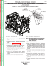
REPLACEMENT PROCEDURE
1. Carefully place the transformer into the
POWER WAVE 655/R.
2. Install the two mounting screws that hold the
transformer to the machine base using the 3/8”
nut driver.
3. Connect leads 33 and 32 to circuit breaker CB4
and the 115 V receptacle.
4. Connect plugs P50 and P52.
5. Reposition any leads and install cable ties as
necessary.
6. Replace the case back.
7. Replace the case top, sides, and input access
panel.
TROUBLESHOOTING & REPAIR
F-52 F-52
POWER WAVE 655/R
Return to Section TOC Return to Section TOC Return to Section TOC Return to Section TOC
Return to Master TOC Return to Master TOC Return to Master TOC Return to Master TOC