


OPERATION
B-5 B-5
POWER WAVE 655/R
Return to Section TOC Return to Section TOC Return to Section TOC Return to Section TOC
Return to Master TOC Return to Master TOC Return to Master TOC Return to Master TOC
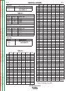
Light
Condition
Steady Green
Blinking
Green
Alternating
Green and
Red
Steady Red
Blinking Red
Meaning
System OK. Power source communicating normal-
ly with wire feeder and its components.
Occurs during a reset, and indicates the PW-
655/R is mapping (identifying) each component
in the system. Normal for first 1-10 seconds
after power is turned on, or if the system con-
figuration is changed during operation.
Non-recoverable system fault. If the PS
Status light is flashing any combination of red
and green, errors are present in the PW-
655/R. Read the error code before the
machine is turned off.
Error Code interpretation through the Status
light is detailed in the Service Manual.
Individual code digits are flashed in red with a
long pause between digits. If more than one
code is present, the codes will be separated
by a green light.
To clear the error, turn power source off, and
back on to reset. See Troubleshooting
Section.
Not applicable.
Not applicable.
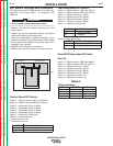
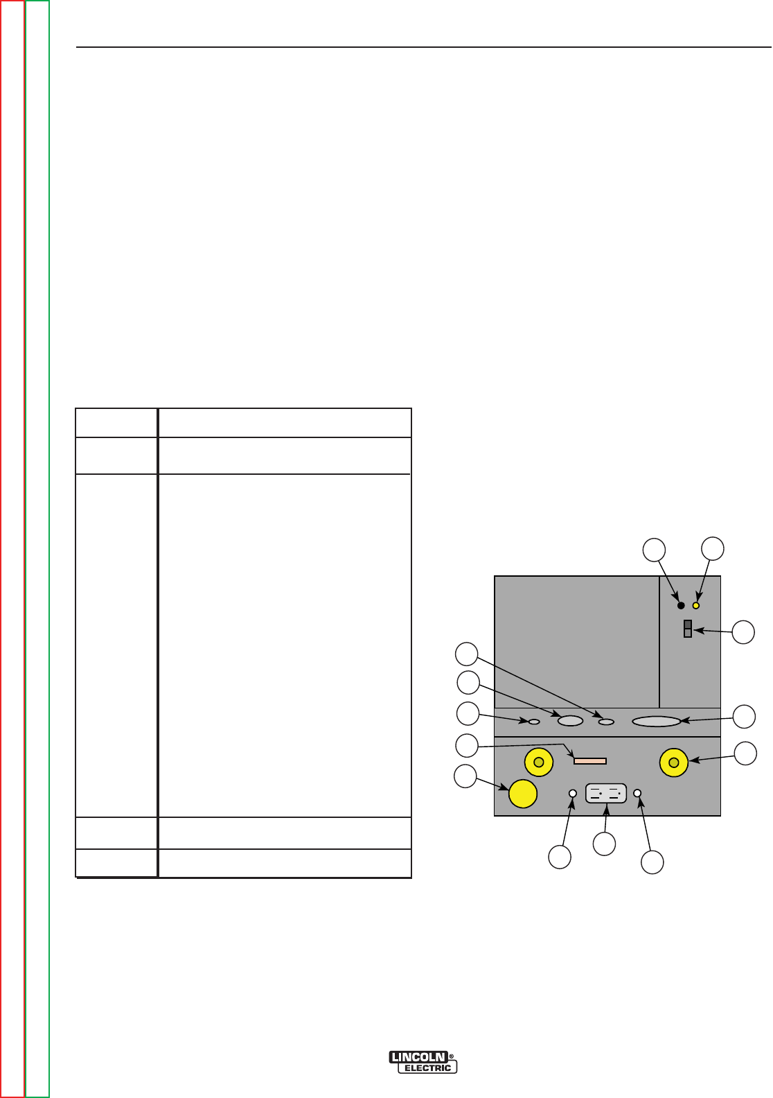
3. HIGH TEMPERATURE LIGHT (thermal overload):
A yellow light that comes on when an over temper-
ature situation occurs. Output is disabled until the
machine cools down. When cool, the light goes out
and output is enabled.
4. 10 AMP WIRE FEEDER CIRCUIT BREAKER:
Protects 40 volt DC wire feeder power supply.
5.
10 AMP AUXILIARY POWER CIRCUIT BREAKER:
Protects 110 volt AC case front receptacle auxiliary
supply.
6. LEAD CONNECTOR S2 (SENSE LEAD)
7. 5-PIN ARC LINK S1
8. 5-PIN DEVICENET CONNECTOR S5
9. I / O CONNECTOR
10. NEGATIVE STUD
11. INTERFACE CONNECTOR S6
12. POSITIVE STUD
13. AUXILIARY OUTPUT
-
+
POWERWAVE
STUD
SENSE
5
LINK
5
Case Front Layout
Power Wave 655/R (Domestic/Canadian Version)
S6
1
3
2
11
12
4
13
5
9
10
8
7
6
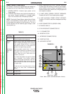
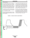
FIGURE B.1
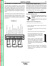
CASE FRONT CONTROLS
All operator controls and adjustments are located on
the case front of the Power Wave. (See Figure B.1)
1. POWER SWITCH: Controls input power to the
Power Wave.
2. STATUS LIGHT: A two color light that indicates sys-
tem errors. Normal operation is a steady green
light. Error conditions are indicated per table 4.
NOTE: The robotic Power Waveʼs status light will flash
green, and sometimes red and green, for up to one
minute when the machine is first turned on. This is a
normal situation as the machine goes through a self
test at power up.
TABLE 6