


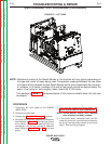
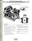

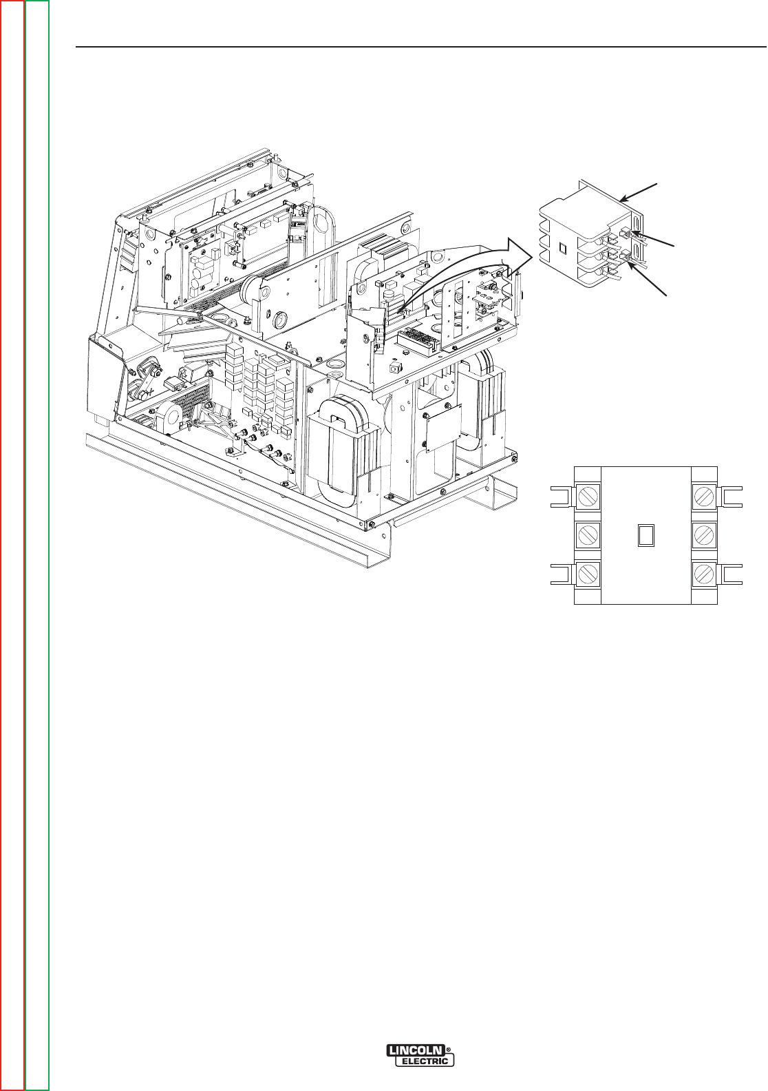
INPUT
CONTACTOR
601
X4
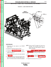
FIGURE F.5 – INPUT CONTACTOR COIL
INPUT CONTACTOR TEST PROCEDURE (CONTINUED)
PROCEDURE
1. Disconnect the input power to the POWER
WAVE 655/R.
2. Remove the input access panel and case top.
3. Locate, mark, and remove the two leads (601,
X4) that are connected to the input contactor
coil. Refer to Figure F.5.
4. Use an ohmmeter to check the resistance of the
coil. It should be approximately 6Ω.
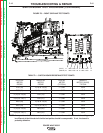
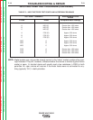
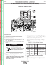
5. Check the resistance across the contacts:
Refer to Figure F.5A
L1 to T1 , L2 to T2 and L3 to T3.
All three readings should show “open”
If the resistance is low, the input contactor is
faulty.
6. Press in on the “test button” and recheck the
contacts as in Step 5.
NOTE: If a 24 vac supply is available, it can be
connected to the coil terminals to activate
the contactor, instead of using the Test
Button.
All readings should be very close to 0Ω
If the resistance is high, the input contactor is
faulty.
7. Reconnect the two leads (601, X4) to the input
contactor coil.
8. Replace the input access door and case top.
TROUBLESHOOTING & REPAIR
F-22 F-22
POWER WAVE 655/R
Return to Section TOC Return to Section TOC Return to Section TOC Return to Section TOC
Return to Master TOC Return to Master TOC Return to Master TOC Return to Master TOC
L3
L2
L1
T3
T2
T1
FFIIGGUURREE FF..55AA
CCOONNTTAACCTTOORR
TTEESSTT PPOOIINNTTSS