


THEORY OF OPERATION
E-3 E-3
POWER WAVE 655/R
Return to Section TOC Return to Section TOC Return to Section TOC Return to Section TOC
Return to Master TOC Return to Master TOC Return to Master TOC Return to Master TOC
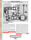
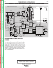
INPUT VOLTAGE AND
PRECHARGE
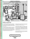
The Power Wave 655/R can be connected for a variety
of three-phase input voltages. Refer to Figure E.2.
The initial input power is applied through a line switch
located on the front of the machine. Two phases of the
three-phase input power are applied simultaneously to
the Input Board and both auxiliary transformers.
The various secondary voltages developed by trans-
former T1 are applied to the Input Board, the fan motor
(via a control relay) and the Bus Board rectifier. The
65VDC produced from the Bus Board rectifier is used
by the Bus Board to provide various DC voltages for
the Power Board, the Feed Head Board, the
Ethernet/Gateway Board and the wire feeder recepta-
cle.
The 115/230VAC developed on the secondary of auxil-
iary transformer T2 is applied to the 115VAC receptacle
and to the water cooler receptacle.
The 230VAC supply is also used to operate an auxil-
iary cooling fan in the upper section of the machine.
This fan runs whenever the power switch is ON.
The large fan in the lower section only runs when the
machine is producing output. It is activated through a
solid state relay that responds to a signal from the
Control Board.
Two of the input lines are connected to the Input Board,
by way of the input line switch SW1. They are then con-
nected to the input rectifier through the precharge relay
on the Input Board. During the precharge or "soft start"
sequence, these two phases are current limited by
resistord on the Input Board.
The AC input voltage is rectified, and the resultant DC
voltage is applied through a harmonic filter to the input
capacitors located on the right and left switch boards.
A Voltage to Frequency circuit on the Switch Boards
sends a signal to the Control Board. When the capaci-
tors have charged to an acceptable level, the Control
Board signals the Input Board to energize the main
input contactor (CR-1). At this point the Power Wave
655/R is in the "Run Mode" of operation. If the capaci-
tors become undervoltaged, overvoltaged, or unbal-
anced, the Control Board will signal the Input Board to
de-energize the main input contactor, and the Power
Wave 655/R will be disabled. See Figure E.2.