


INPUT
CONTACTOR
601
X4
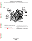
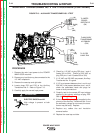
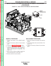
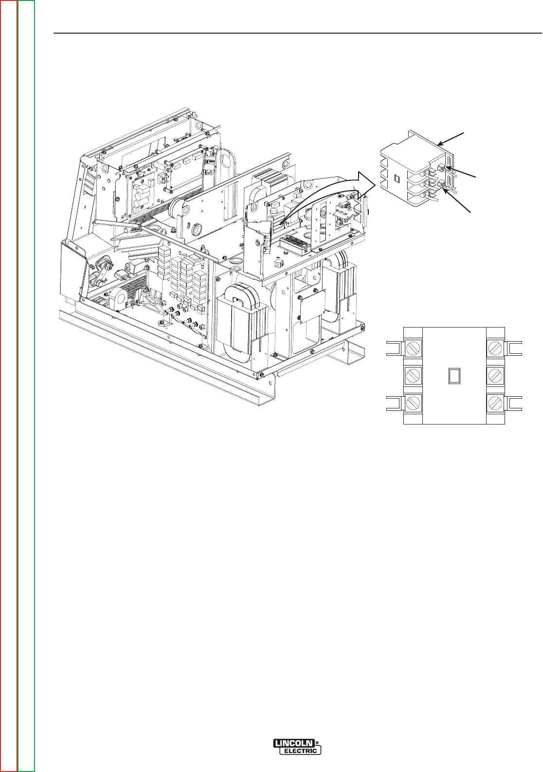
FIGURE F.15 – INPUT CONTACTOR REMOVAL AND REPLACEMENT
INPUT CONTACTOR REMOVAL AND REPLACEMENT PROCEDURE
(CONTINUED)
REMOVAL PROCEDURE
1. Remove input power to the POWER WAVE
655/R.
2. Remove the case top, sides and input access
panel.
3. Perform the Capacitor Discharge procedure
4. Locate the input contactor. Label and carefully
remove the leads from the input contactor ter-
minals. Note placement for reassembly. See
Figure F.15.
5. With a 5/16” nut driver or socket, remove the
three mounting screws. See Figure F.15.
6. Carefully remove the input contactor.
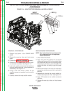
REPLACEMENT PROCEDURE
1. Mount the contactor and tighten the mounting
screws.
2. Connect the leads to the correct terminals. See
Figure F.15.
3. Replace the case top, sides and input access
panel.
TROUBLESHOOTING & REPAIR
F-48 F-48
POWER WAVE 655/R
Return to Section TOC Return to Section TOC Return to Section TOC Return to Section TOC
Return to Master TOC Return to Master TOC Return to Master TOC Return to Master TOC
L3
L2
L1
T3
T2
T1