


A1
C13
L1
C15
R12
R9
R10
R11
R25
D1
D2
DZ4
C6
R4
R5
R7
R8
R19
X1
X2
C2
C3
C5
C7
C8
C9
C10
C11
MOV1
LED1
R3
R13
R14
R20
R21
R22
R23
DZ5
DZ6
R15 R16
D3
J47 J46
C14
C16
C17
D4
D5
MOV2
R26
R27
R28
R29
C1
LED
J47
J46
1
2
1
2
3
4
5
6
7
8
3
4
C3
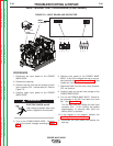
Power Bd.
Rectier
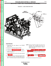
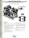
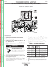
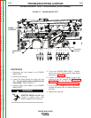
FIGURE F.6 – DC BUS PC BOARD
DC BUS BOARD TEST PROCEDURE (CONTINUED)
TROUBLESHOOTING & REPAIR
F-24 F-24
POWER WAVE 655/R
Return to Section TOC Return to Section TOC Return to Section TOC Return to Section TOC
Return to Master TOC Return to Master TOC Return to Master TOC Return to Master TOC
PROCEDURE
1. Disconnect the input power from the machine.
2. Remove the case top.
3. Locate the DC Bus PC Board and plugs P46 and
P47. See Figure F.6.
4. Carefully apply input power to the POWER WAVE
655/R.
ELECTRIC SHOCK can kill.
High voltage is present when input
power is applied to the machine.
5. Turn on the POWER WAVE 655/R. The LED on the
DC Bus Board should light.
If the LED does not light, check the input voltage to
the board at the terminals of the capacitor C-3. It
should read 65-75vdc.
6. If the input voltage is correct the DC Bus Board may
be defective. If not, check the Power Board
Rectifier and the Auxiliary Transformer T1.
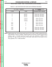
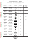
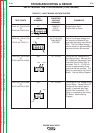
7. Check the Bus Board output voltages at P47 per
Table F.3.
8. If any of the readings is incorrect, replace the
board.
9. Disconnect the input power and replace the case
top.
WARNING
Positive
Meter
Probe
Negative
Meter
Probe
Voltage
Reading
(vdc)
Pin 7 Pin 6 38 to 42 to Power PC Bd.
Pin 8 Pin 6 38 to42 to Power PC Bd.
Pin 4 Pin 2 38 to 42 to Feed Head Bd.
Pin 3 Pin 1 38 to 42
to S1 - Wire Feeder
Receptacle
TABLE F.3 - DC Bus Bd Output Voltages