


THEORY OF OPERATION
E-2 E-2
POWER WAVE 655/R
Return to Section TOC Return to Section TOC Return to Section TOC Return to Section TOC
Return to Master TOC Return to Master TOC Return to Master TOC Return to Master TOC
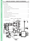
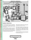
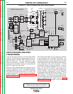
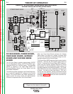
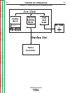
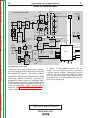
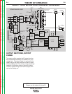
NOTE: Unshaded areas of Block Logic
Diagram are the subject of discussion
GENERAL DESCRIPTION
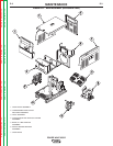
The Power Wave 655/R power source is designed to
be a part of a modular, multi-process welding system.
It is a high performance, digitally controlled inverter
welding power source capable of complex, high-speed
waveform control.
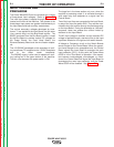
The Power Wave 655/R is designed to be used with
the family of Power Feed wire feeders, operating as a
system. Each component in the system has special cir-
cuitry to "talk with" the other system components, so
each component (power source, wire feeder, electrical
accessories) knows what the other is doing at all times.
The components communicate with Arc-Link.
Robotic systems can communicate with other industri-
al machines via DeviceNET or Arc Link. The result is
highly integrated and flexible welding cell.
Depending upon configuration, it can support constant
current, constant voltage, and pulse welding modes.
Each machine is factory preprogrammed with multiple
welding procedures. Typically these procedures
include GMAW, GMAW-P, FCAW, GTAW for a variety
of materials such as mild steel, stainless steel, cored
wires and aluminum.
The Power Wave 655/R has an output rating of either
650 amps at 44 (at 100% duty cycle) volts or 800 amps
at 44 volts (at 60% duty cycle.
FIGURE E.2 – INPUT VOLTAGE AND PRECHARGE
+
INPUT
B
OARD
LEFT
SWITCH
B
OARD
RIGHT
SWITCH
BOARD
INPUT
R
ECTIFIER
C
R1
GATEWAY
BOARD
DC
BUS
BOARD
FEED
HEAD
BOARD
P
OWER
BOARD
CONTROL
BOARD
OUTPUT
C
HOKE
E
LECTRODE
TERMINAL
T
HERMOSTATS
T1
T2
AUX
R
ECONNECT
R
ELAY
WATER
C
OOLER
115VAC
RECP.
1
15VAC
FAN
ARC LINK
WIRE
FEEDER
RECP.
S1
S6
CONNECTION
TO WIRE
DRIVE
S
1
S6
V
OLT
SENSE
B
OARD
MAIN
TRANSFORMER
S5
CONTACTOR AND PRECHARGE
CONTROL SIGNALS FROM
CONTROL BOARD
FROM CONTROL
BOARD
2
4
V
A
C
1
15 VAC
5
2 VAC
230 VAC
40 VDC
40 VDC
40 VDC
40 VDC
ARC LINK
CONNECTION
TO
ROBOT
VOLTAGE SENSE
OUTPUT
CAP.V/F
FEEDBACK
CAP.V/F
FEEDBACK
IGBT DRIVE
FROM
CONTROL
BOARD
CT CURRENT
TO CONTROL
BOARD
-15 V
+15 V
+
5 V
+5 V ARC LINK
+5V RS232
+
15V SPI
STATUS THERMAL
LIGHT LIGHT
S2 WORK
SENSE
LEFT S.B.
C
AP.V/F
R
IGHT S.B.
CAP.V/F
S3
RS232
L
EFT CT
CURRENT
FB
C
U
R
R
E
N
T
F
B
ARC LINK
IGBT
D
RIVES
TO
LEFT
S.B.
T
O
R
IGHT
S
.B.
67A
67B
SW1
B
US BOARD
R
ECTIFIER
CURRENT
TRANSDUCER
O
UTPUT DIODES
D1 -D4
1
15 VAC
4
0 VDC
DEVICE NET
VOLTAGE SENSE SELECT
IGBT DRIVE
FROM
CONTROL
BOARD
+
5V SPI
RIGHT CT
CURRENT
FB
TO FAN RELAY
C
ONTACTOR AND
P
RECHARGE
C
ONTROL SIGNALS
65 VDC
WORK
T
ERMINAL
POWER WAVE 655/R
380-
415
440-
460
550-
575
+
ETHERNET/
A
A
HARMONIC
FILTER
C
POS
N
EG
Auxiliary
Fan