


THEORY OF OPERATION
E-4 E-4
POWER WAVE 655/R
Return to Section TOC Return to Section TOC Return to Section TOC Return to Section TOC
Return to Master TOC Return to Master TOC Return to Master TOC Return to Master TOC
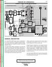
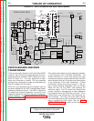
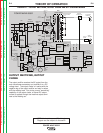
NOTE: Unshaded areas of Block Logic
Diagram are the subject of discussion
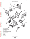
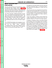
SWITCH BOARDS AND MAIN
TRANSFORMER
There are two switch boards in the Power Wave 655/R
machine. Each contains two input capacitors and insu-
lated gate bipolar transistor (IGBT) switching circuitry.
Refer to Figure E.3. The input capacitors on each
board are connected in parallel. The two paralleled
pairs are then connected in series to accomodate the
high DC voltage from the rectifier.
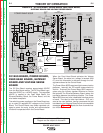
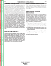
When the input capacitors are fully charged, they act
as power supplies for the IGBT (insulated gate bipolar
transistors) switching circuits. The IGBTʼs switch the
DC power from the input capacitors "on and off," thus
supplying pulsed DC current to the main transformer
primary windings. See IGBT OPERATION DISCUS-
SION AND DIAGRAMS in this section.
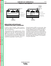
Each switch board feeds current to separate, opposite-
ly wound primary coils in the Main Transformer. The
reverse directions of current flow through the main
transformer primaries, and the offset timing of the IGBT
switch boards induce an AC square wave output signal
at the secondary of the main transformer. Current
transformers monitor the primary currents. If the pri-
mary currents become abnormally high, the Control
Board will shut off the IGBTs, thus disabling the
machineʼs output. The DC current flow through each
primary winding is clamped back to each respective
input capacitor when the IGBTs are turned off. This is
needed due to the inductance of the transformer pri-
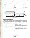
mary windings. The firing of the two switch boards
occurs during halves of a 50-microsecond interval, cre-
ating a constant 20 KHZ output. See the PULSE
WIDTH MODULATION discussion in this section.
FIGURE E.3 - SWITCH BOARDS AND MAIN TRANSFORMER
+
INPUT
BOARD
LEFT
S
WITCH
BOARD
RIGHT
SWITCH
BOARD
INPUT
RECTIFIER
C
R1
G
ATEWAY
BOARD
DC
BUS
BOARD
FEED
HEAD
BOARD
POWER
B
OARD
C
ONTROL
BOARD
OUTPUT
C
HOKE
ELECTRODE
TERMINAL
THERMOSTATS
T
1
T2
AUX
RECONNECT
RELAY
WATER
COOLER
1
15 VAC
RECP.
115 VAC
FAN
ARC LINK
W
IRE
F
EEDER
R
ECP.
S1
S6
CONNECTION
TO WIRE
DRIVE
S1
S6
VOLT
S
ENSE
B
OARD
MAIN
TRANSFORMER
S
5
CONTACTOR AND PRECHARGE
CONTROL SIGNALS FROM
CONTROL BOARD
FROM CONTROL
BOARD
2
4
V
A
C
115 VAC
52 VAC
230 VAC
40 VDC
40 VDC
40 VDC
40 VDC
ARC LINK
CONNECTION
T
O
ROBOT
VOLTA GE SENSE
OUTPUT
CAP.V/F
FEEDBACK
CAP.V/F
FEEDBACK
IGBT DRIVE
FROM
CONTROL
BOARD
CT CURRENT
T
O CONTROL
BOARD
-15 V
+15 V
+5 V
+5 V ARC LINK
+
5V RS232
+15V SPI
STATUS THERMAL
LIGHT LIGHT
S2 WORK
SENSE
LEFT S.B.
CAP.V/F
RIGHT S.B.
CAP.V/F
S3
RS232
LEFT CT
CURRENT
FB
C
U
R
R
E
N
T
F
B
ARC LINK
IGBT
D
RIVES
TO
LEFT
S.B.
TO
RIGHT
S.B.
67A
67B
SW1
BUS BOARD
RECTIFIER
CURRENT
TRANSDUCER
OUTPUT DIODES
D1 -D4
115 VAC
40 VDC
DEVICE NET
VOLTA GE SENSE SELECT
IGBT DRIVE
FROM
CONTROL
BOARD
+5V SPI
RIGHT CT
CURRENT
FB
TO FAN RELAY
CONTACTOR AND
PRECHARGE
CONTROL SIGNALS
65 VDC
W
ORK
T
ERMINAL
POWER WAVE 655/R
3
80-
415
440-
460
5
50-
575
+
E
THERNET/
A
A
H
ARMONIC
FILTER
C
P
OS
NEG
A
uxiliary
Fan