


INSTALLATION
A-9 A-9
POWER WAVE 655/R
Return to Section TOC Return to Section TOC Return to Section TOC Return to Section TOC
Return to Master TOC Return to Master TOC Return to Master TOC Return to Master TOC
HIGH SPEED GEAR BOX
Changing the ratio requires a gear change and a PC
board switch change. The Power Feed Wire Feeders
are shipped with both high speed and a low speed
gears. As shipped from the factory, the low speed (high
torque) gear is installed on the feeder. To change Gear
ratio see Power Feed 10/R Instruction Manual.
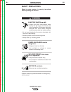
ELECTRIC SHOCK can kill.
• Do not touch electrically live parts or
electrodes with your skin or wet
clothing.
• Insulate yourself from the work and
ground.
• Always wear dry insulating gloves.
-----------------------------------------------------------
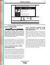
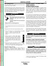
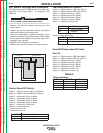
1. Set the High/Low switch code on Wire Drive PC
board as follows:
• Turn off power to the power source at the discon-
nect switch.
• Remove the front cover from the power source.
• The wire feed head board is on the right
side of the power source. Locate the 8-
position DIP switch and look for position
8 of the DIP switch.
• Using a pencil or other small object,
slide the switch right to the OFF position,
when the low speed gear is installed.
Conversely, slide the switch left to the
ON position when the high speed gear is
installed.
• Replace the cover and screws. The PC board will
“read” the switch at power up, automatically
adjusting all control parameters for the speed
range selected.
O
N
1 2 3 4 5 6 7 8
WARNING
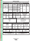
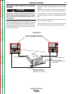
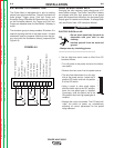
EXTERNAL I/O CONNECTOR
The Power Wave is equipped with a port for making
simple input signal connections. The port is divided into
three groups: Trigger group, Cold Inch Group and
Shutdown Group. Because the Power Wave is a ʻslaveʼ
on the DeviceNet network, the Trigger and Cold Inch
Groups are disabled when the DeviceNet / Gateway is
active.
The shutdown group is always enabled. Shutdown 2 is
used for signaling low flow in the water cooler. Unused
shutdowns must be jumpered. Machines from the fac-
tory come with the shutdowns already jumpered.(See
Figure A.5)
D
E
F
1
2
3
4
5
6
78
910
11
12
G
H
I
A
B
C
+15 VDC for Trigger Group
Trigger Input
Dual Procedure Input
4 Step Input
+15 VDC for Cold Inch Group
Cold Inch Forward
Cold Inch Reverse
Gas Purge Input
+15 for shutdown group
Shutdown1 input
Shutdown2 input (Water Fault)
Reserved for future use
FIGURE A.5