


INSTALLATION
A-5 A-5
POWER WAVE 655/R
Return to Section TOC Return to Section TOC Return to Section TOC Return to Section TOC
Return to Master TOC Return to Master TOC Return to Master TOC Return to Master TOC
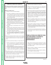
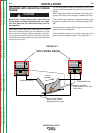
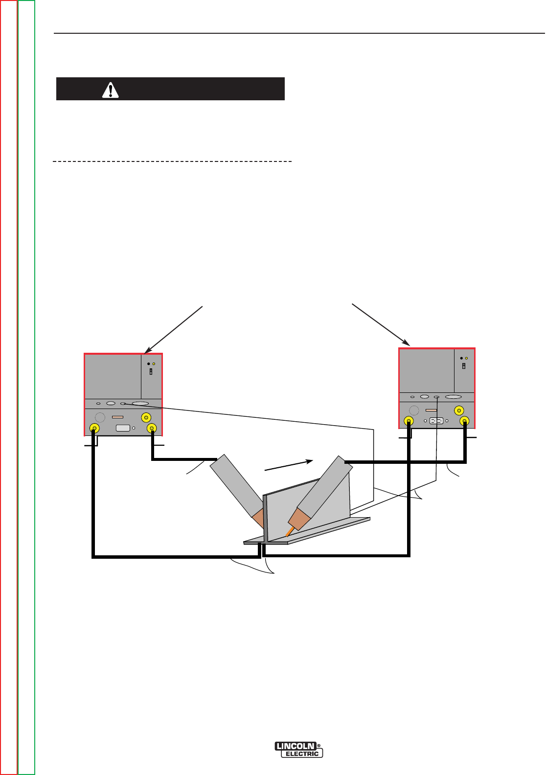
WELDING WITH MULTIPLE POWER
WAVES
Special care must be taken when more than one
Power Wave is welding simultaneously on a single
part. Arc blow and arc interference may occur or
be magnified.
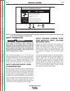
Each power source requires a work lead from the work
stud to the welding fixture. Do not combine all of the
work leads into one lead. Perform welding in the direc-
tion away from the work leads. Connect all of the work
sense leads from each power source to the work piece
at the end of the joint.
-
+
POWERWAVE
-
+
POWERWAVE
Connect All Work
Sense
Electrode Lead
Electrode Lead
Leads at the End
of
the Joint
Connect All Welding
Work Leads at the
Beginning of the Joint
Travel
Direction
TWO POWER WAVES
For the best results when pulse welding, set the wire
size and wire feed speed the same for all the Power
Waves.
When these parameters are identical, the pulsing fre-
quency will be the same, helping to stabilize the arcs.
Every welding gun requires a separate shielding gas
regulator for proper flow rate and shielding gas cover-
age.
Do not attempt to supply shielding gas for two or more
guns from only one regulator.
If an anti-spatter system is in use then each gun must
have its own anti-spatter system. (See Figure A.2.)
CAUTION
FIGURE A.2