


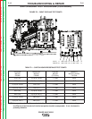
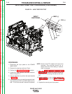
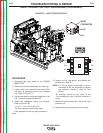
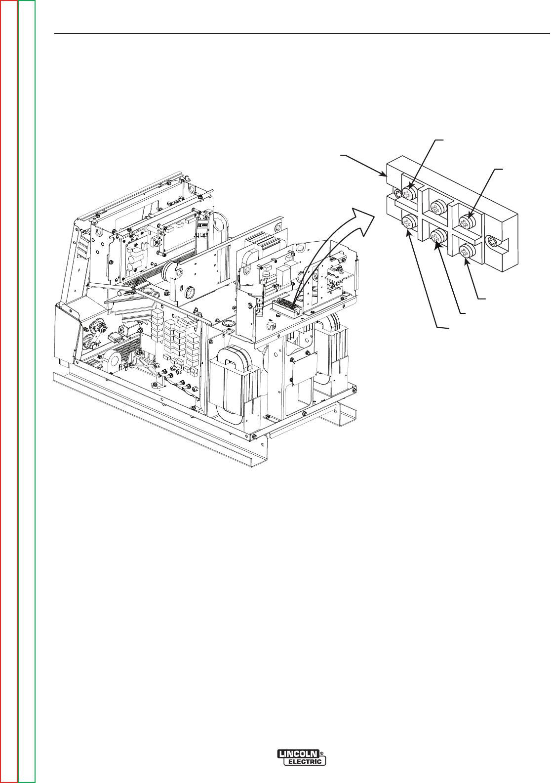
NEG (-)
A
B
C
INPUT
RECTIFIER
POS (+)
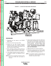
FIGURE F.4 – INPUT RECTIFIER TEST
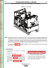
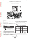
INPUT RECTIFIER TEST PROCEDURE (CONTINUED)
PROCEDURE
1. Disconnect the input power to the POWER
WAVE 655/R.
2. Remove the case top and Input Panel.
3. Perform the Capacitor Discharge Procedure.
4. Locate the Input Rectifier and lead locations.
Refer to Figure F.4.
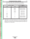
5. Use an ohmmeter to perform the tests detailed
in Table F.2.
6. If the rectifier does not meet the expected read-
ings,remove the POS. and NEG leads and re-
test. If it still fails the test it should be replaced.
NOTE: Some of the RTV material will have to be
removed. The terminals should be re-
sealed with RTV when testing or replace-
ment is complete.
9. See the Input Rectifier Removal and
Replacement procedure for proper torque set-
tings when re-connecting the leads to the recti-
fier.
10. Before installing a new rectifier, perform the
Switch Board test and the Input Contactor
test.
11. Replace the case top and input panel.
TROUBLESHOOTING & REPAIR
F-18 F-18
POWER WAVE 655/R
Return to Section TOC Return to Section TOC Return to Section TOC Return to Section TOC
Return to Master TOC Return to Master TOC Return to Master TOC Return to Master TOC