


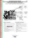
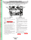
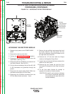

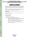

CURRENT
TRANSDUCER
+
THIS SIDE
FACES
REAR
FIGURE F.20 – POWER WAVE CURRENT TRANSDUCER REMOVAL
AND REPLACEMENT PROCEDURE
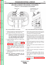
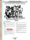
CURRENT TRANSDUCER
REMOVAL AND REPLACEMENT PROCEDURE (CONTINUED)
REMOVAL PROCEDURE
1. Remove input power to the POWER WAVE
655/R.
2. Remove the case sides.
3. Perform the Capacitor Discharge procedure.
4. Remove the 1/2” bolt that holds the 4/0 cable to
the back of the lower right (+) Output Stud.
5. Cut the tie wrap that holds the harness to the
transducer and disconnect P91.
6. Using a phillips head screw driver, remove the
screws and lock washers that hold the trans-
ducer to the machine base.
7. Side the current transducer off of the 4/0 cable,
noting the direction of the current flow indicator
(arrow).
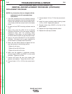
REPLACEMENT PROCEDURE
1. Slide the new Transducer over the 4/0 cable. Be
certain that the current flow indictor (arrow)
points towards the back of the machine. See
Figure F.20.
2. Mount the Transducer to the machine base with
the two Phillips head screws.
3. Re-connect the 4/0 cable to the Output Stud.
4. Carefully re-connect the 4 pin connector (P-91)
to the Transducer and secure the harness with
a tie wrap.
5. Replace the case sides.
TROUBLESHOOTING & REPAIR
F-58 F-58
POWER WAVE 655/R
Return to Section TOC Return to Section TOC Return to Section TOC Return to Section TOC
Return to Master TOC Return to Master TOC Return to Master TOC Return to Master TOC