


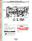

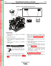
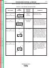
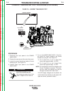
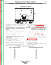
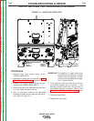
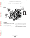
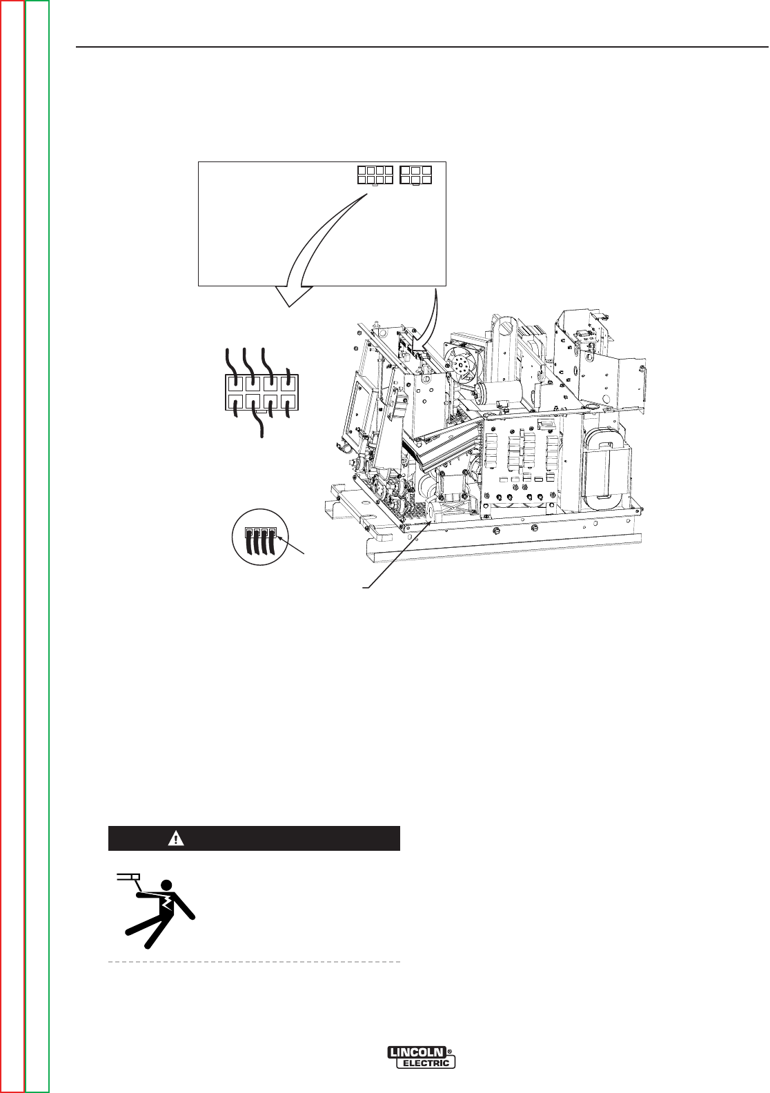
FIGURE F.9 – CURRENT TRANSDUCER TEST
CURRENT TRANSDUCER TEST PROCEDURE (CONTINUED)
PROCEDURE
1. Disconnect the input power to the POWER
WAVE 655/R.
2. Remove the case top and the control box cover.
3. Locate the current transducer leads at Control
Board plug J8. See Figure F.9.
4. Carefully apply input power to the POWER
WAVE 655/R.
ELECTRIC SHOCK can kill.
High voltage is present when input
power is applied to the machine.
5. Turn on the POWER WAVE 655/R. Check for
the correct DC supply voltage to the current
transducer at plug J8. See Figure F.9.
A. Pin 2 (lead 212+) to pin 6 (lead 216-)
should read approximately +15 VDC.
B. Pin 3 (lead 213-) to pin 6 (lead 216+)
should read approximately -15 VDC.
NOTE: Do not attempt to check the voltages at the
Current Transducer connector. The termi-
nals are small and delicate and may be
damaged if probed with meter leads.
If the DC supply voltages are not present, the
control board may be faulty. If the supply volt-
ages are correct, procede to Step 6.
TROUBLESHOOTING & REPAIR
F-34 F-34
POWER WAVE 655/R
Return to Section TOC Return to Section TOC Return to Section TOC Return to Section TOC
Return to Master TOC Return to Master TOC Return to Master TOC Return to Master TOC
CURRENT
TRANSDUCER
J8
216
211
212
213
CONTROL BOARD
J8
5 6 7 8
1 2 3 4
P91
1234
J9
WARNING