


CALIBRATION PROCEDURE (CONTINUED)
TROUBLESHOOTING & REPAIR
F-68 F-68
POWER WAVE 655/R
Return to Section TOC Return to Section TOC Return to Section TOC Return to Section TOC
Return to Master TOC Return to Master TOC Return to Master TOC Return to Master TOC
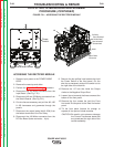
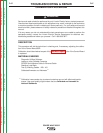
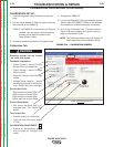
FIGURE F.24 – CALIBRATION SCREEN
Calibration Tab
Machine output can be turned
“on” with this screen.
Feedback Information
• Output Current – Value of Current
Sensor Device (transducer).
• Output Voltage – Value of Voltage
Sensing point.
• Capacitor Group A and B Voltage
values
• Voltage Sense Location – should
be sensing at studs for calibration
(use “Cable Test” tab to change.)
Current Set Point:
350A machine choose 300A
450A machine choose 300A
650A machine choose 300A
1000A machine choose 500A
Current Weld Mode
• Will always be mode 200 (c.c.)
activated from “Turn Output On”
button
Turn Output ON
• Enables output for calibration
• Light will flash Red when output
is “ON”
CALIBRATION ADJUSTMENT
• System will automaticaly adjust
output levels as changes are
made
WARNING
Light is BLACK when OFF.
▲
▲
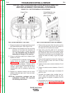
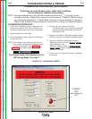
CALIBRATION SET-UP:
1. Load the Diagnostic Utility Software into the com-
puter.
2. Use the Serial Modem or Ethernet cable to connect
the computer to the PW655-R.
NOTE: If the PW655-R is connected to an Ethernet
network, you may use an ethernet cable to
connect to the machine instead of the
Serial Modem Cable.
3. Connect a resistive load bank to the output studs.
4. Energize the PW655-R.
5. Launch the Diagnostic Utility and establish commu-
nication with the PW655-R. (Refer to the Software
Documentation to determine proper connection)
6. Click on the “Calibration” tab. A screen similar to
Figure F.24 should appear and you are ready to
begin the Calibration check
NOTE: The Calibration Screen may look slightly dif-
ferent depending on the software version.