


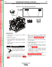

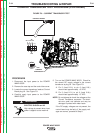

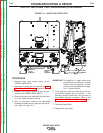


FIGURE F.10 – RS 232 port
CURRENT TRANSDUCER TEST PROCEDURE (CONTINUED)
TROUBLESHOOTING & REPAIR
F-35 F-35
POWER WAVE 655/R
Return to Section TOC Return to Section TOC Return to Section TOC Return to Section TOC
Return to Master TOC Return to Master TOC Return to Master TOC Return to Master TOC
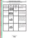
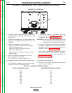
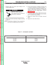
TABLE F.6 - CURRENT FEEDBACK CHART
OUTPUT CURRENT (Actual)
500
450
400
350
300
250
200
150
100
50
EXPECTED FEEDBACK VOLTAGE
4.0
3.6
3.2
2.8
2.4
2.0
1.6
1.2
0.8
0.4
6. Connect a laptop computer to the PW655-R via
the RS232 port on the front of the machine. See
Figure F.10.
7. Connect a Load Bank (or 50ʼ weld cable) to the
Positive and Negative Output Studs of the
PW655-R.
8. Using the “Diagnostic Utility Software:
Establish Communication with the PW655R
Select the ʻCalibrateʼ tab.
Select the ʻ50 ampʼ Current Set Point
Select ʻTurn Output ONʼ
Use an external calibrated ammeter to read
actual current
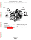
9. Check the feedback voltage at the Control
Board plug J8 per Table F.6.
Pin 1 (lead 211 +) to pin 6 (lead 216 -).
10. Repeat the test at several other current levels.
If the feedback voltage is correct for the actual
current, the Current Transducer is OK
If the feeback voltage is not present, check the
wiring from the Control Board to the Current
Transducer, See the Wiring Diagram.
CAUTION: If using a weld cable across the output
studs instead of a Load Bank, do not
exceed the current rating of the cable.
11. If supply voltages are correct but feedback
voltages are incorrect, the Current Transducer or
wiring from P91 to the Control Board may be
defective. See the Wiring Diagram.
If the ʻactualʼ (measured) current does not match
the ʻsetʼ current but the feedback voltage is
correct for the actual current, perform the
Machine Calibration.
12. Click on “Turn Output Off”
13. Disconnect the computer.
14. Remove input power and replace the control
box cover and case top.
RS 232
PORT