


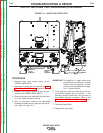

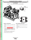

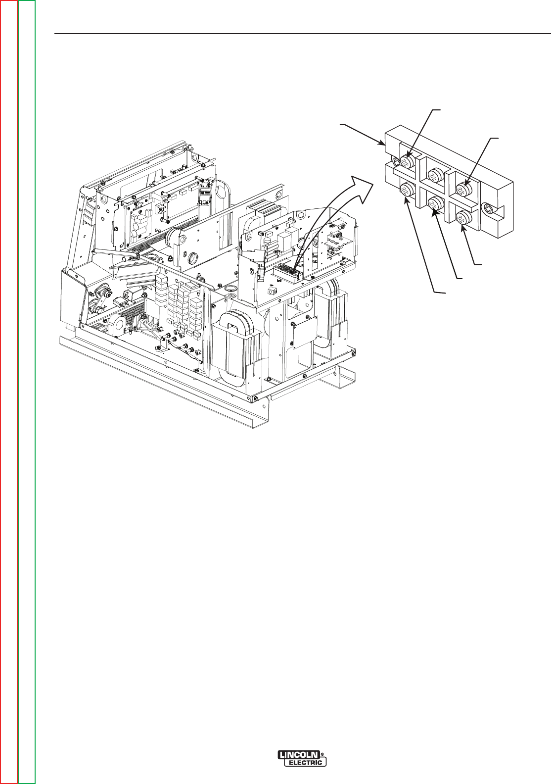
NEG (-)
A
B
C
INPUT
RECTIFIER
POS (+)
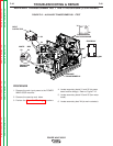
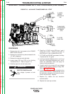
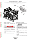
FIGURE F.14 – INPUT RECTIFIER REMOVAL AND REPLACEMENT
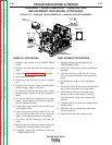
INPUT RECTIFIER REMOVAL AND REPLACEMENT PROCEDURE
(CONTINUED)
REMOVAL PROCEDURE
1. Remove input power to the POWER WAVE
655/R.
2. Remove the case top, sides, and input access
panel.
3. Perform the Capacitor Discharge procedure.
4. Remove the RTV sealant from the input rectifi-
er connection terminals. See Figure F. 14.
5. Label and carefully remove the five leads from
the input rectifier terminals. Note placement for
reassembly. See Figure F.14.
6. Using a 3/16” allen wrench, remove the two
mounting screws and washers from the rectifier
module.
7. Carefully remove the input rectifier module.
REPLACEMENT PROCEDURE
NOTE: Any instructions that are shipped with
the replacement part will supersede
these instructions.
1. Clean heat sink surfaces.
2. Apply a thin, even film (.004” t0 .01”) of thermal
compound (Penetrox A13) to the module. Keep
the compound away from the mounting holes.
Compound in the holes or on the threads of the
screws will affect the ability to get the proper
torque.
3. Mount the module to the heat sink and evenly
torque the mounting screws (with washers) to
44 in/lbs.
4. Assemble the leads to the correct module ter-
minals and torque to 31 in/lbs. See Figure F.14.
5. Apply RTV sealant to the rectifier connection
terminals.
6. Replace the case top, sides, and input access
panel.
TROUBLESHOOTING & REPAIR
F-46 F-46
POWER WAVE 655/R
Return to Section TOC Return to Section TOC Return to Section TOC Return to Section TOC
Return to Master TOC Return to Master TOC Return to Master TOC Return to Master TOC