


THEORY OF OPERATION
E-7 E-7
POWER WAVE 655/R
Return to Section TOC Return to Section TOC Return to Section TOC Return to Section TOC
Return to Master TOC Return to Master TOC Return to Master TOC Return to Master TOC
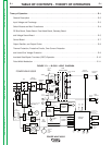
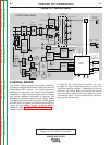
NOTE: Unshaded areas of Block Logic
Diagram are the subject of discussion
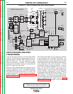
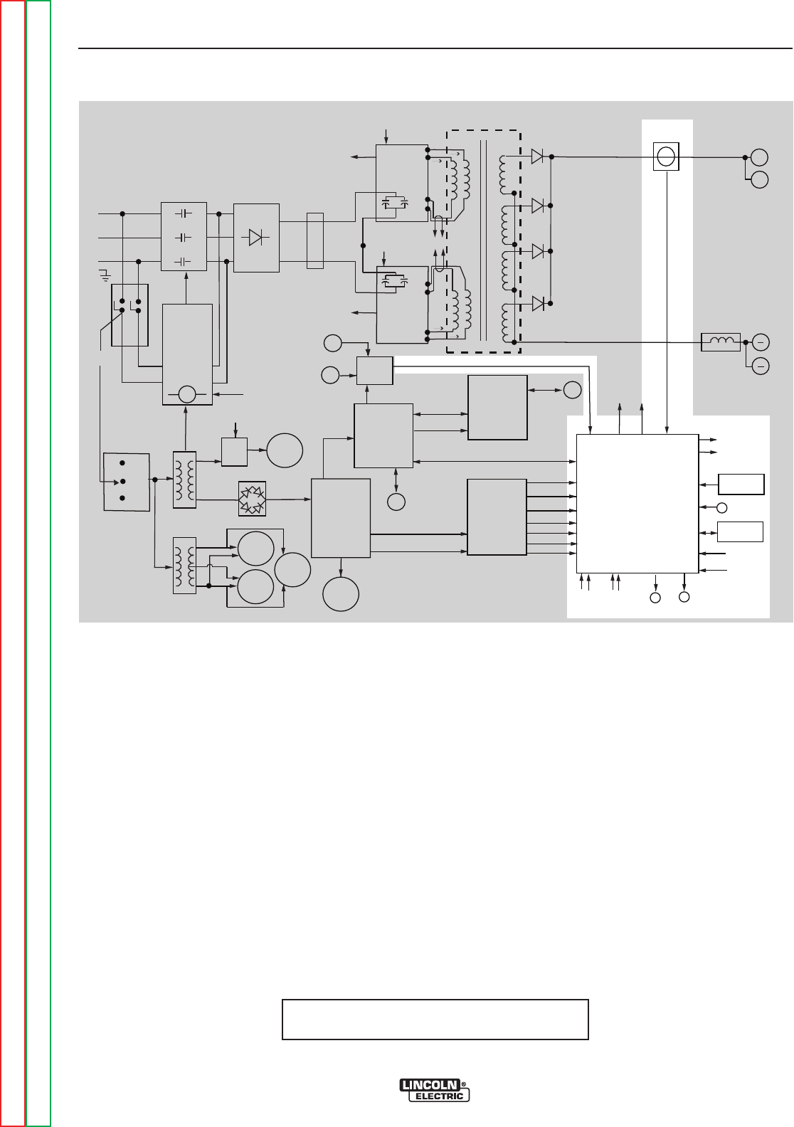
CONTROL BOARD
The Control Board performs the primary interfacing
functions to establish and maintain output control of the
Power Wave 655R machine. The function generator
and weld files exist within the Control Board hardware
and software. Digital command signals and arc voltage
and current feedback information is received and
processed by software located on the Control Board.
The appropriate pulse width modulation (PWM) signals
are then sent to the gates of the Switch Board IGBTs to
create the high-speed, digitally controlled welding
waveform. (See PULSE WIDTH MODULATION dis-
cussion in this section).
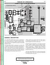
In addition, the Control Board monitors the ther-
mostats, the main transformer primary currents and
input filter capacitor voltages. Depending on the fault
condition, the Control Board will activate the thermal
and/or the status light and will either disable or reduce
the machine output. In some conditions the input con-
tactor will be de-energized.
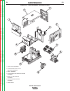
FIGURE E.6 – CONTROL BOARD
+
INPUT
BOARD
LEFT
SWITCH
B
OARD
RIGHT
S
WITCH
BOARD
INPUT
RECTIFIER
C
R1
GATEWAY
BOARD
DC
BUS
B
OARD
FEED
HEAD
B
OARD
POWER
BOARD
CONTROL
BOARD
OUTPUT
CHOKE
ELECTRODE
TERMINAL
THERMOSTATS
T1
T2
AUX
RECONNECT
RELAY
WATER
C
OOLER
1
15VAC
RECP.
1
15VAC
FAN
ARC LINK
WIRE
FEEDER
R
ECP.
S1
S6
CONNECTION
TO WIRE
DRIVE
S1
S6
VOLT
S
ENSE
B
OARD
MAIN
T
RANSFORMER
S5
CONTACTOR AND PRECHARGE
CONTROL SIGNALS FROM
CONTROL BOARD
F
ROM CONTROL
BOARD
2
4
V
A
C
115 VAC
52 VAC
230 VAC
40 VDC
40 VDC
4
0 VDC
40 VDC
ARC LINK
CONNECTION
T
O
ROBOT
VOLTA GE SENSE
OUTPUT
CAP.V/F
F
EEDBACK
CAP.V/F
F
EEDBACK
IGBT DRIVE
FROM
CONTROL
B
OARD
CT CURRENT
TO CONTROL
BOARD
-15 V
+15 V
+5 V
+
5 V ARC LINK
+5V RS232
+15V SPI
STATUS THERMAL
LIGHT LIGHT
S
2 WORK
SENSE
LEFT S.B.
CAP.V/F
RIGHT S.B.
CAP.V/F
S3
RS232
L
EFT CT
CURRENT
FB
C
U
R
R
E
N
T
F
B
A
RC LINK
IGBT
DRIVES
TO
LEFT
S.B.
TO
RIGHT
S.B.
6
7A
67B
S
W1
BUS BOARD
RECTIFIER
CURRENT
TRANSDUCER
O
UTPUT DIODES
D1 -D4
115 VAC
40 VDC
DEVICE NET
VOLTA GE SENSE SELECT
IGBT DRIVE
FROM
C
ONTROL
BOARD
+5V SPI
RIGHT CT
CURRENT
FB
TO FAN RELAY
C
ONTACTOR AND
PRECHARGE
C
ONTROL SIGNALS
65 VDC
W
ORK
T
ERMINAL
POWER WAVE 655/R
380-
415
440-
460
550-
575
+
ETHERNET/
A
A
HARMONIC
FILTER
C
POS
NEG
Auxiliary
Fan