


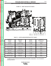
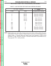

TABLE F.2 – INPUT RECTIFIER TEST POINTS AND ACCEPTABLE READINGS
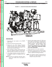
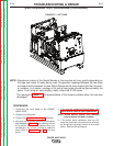
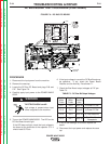
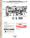
INPUT RECTIFIER TEST PROCEDURE (CONTINUED)
TROUBLESHOOTING & REPAIR
F-19 F-19
POWER WAVE 655/R
Return to Section TOC Return to Section TOC Return to Section TOC Return to Section TOC
Return to Master TOC Return to Master TOC Return to Master TOC Return to Master TOC
TEST POINT TERMINALS
A
B
C
A
B
C
NEG
NEG
NEG
POS
POS
POS
NEG (F)
NEG (F)
NEG (F)
POS (D)
POS (D)
POS (D)
A
B
C
A
B
C
Greater than 1000 ohms
Greater than 1000 ohms
Greater than 1000 ohms
Approx. 500 ohms
Approx. 500 ohms
Approx. 500 ohms
Approx. 500 ohms
Approx. 500 ohms
Approx. 500 ohms
Greater than 1000 ohms
Greater than 1000 ohms
Greater than 1000 ohms
ANALOG METER X100
RANGE
Acceptable Meter Readings
+ Probe - Probe
NOTE: Digital meters may not provide enough current in the “ohms” mode to achieve the read-
ings indicated. They will, however, indicate whether the device is shorted (typical failure
mode) or open. A ʻshortedʼ device will usually read a low resistance (<100Ω) in both
polarities. An ʻopenʼ device will read as if the meter leads were not connected to any-
thing (typically “OL”) in both polarities.