


INSTALLATION
A-10 A-10
POWER WAVE 655/R
Return to Section TOC Return to Section TOC Return to Section TOC Return to Section TOC
Return to Master TOC Return to Master TOC Return to Master TOC Return to Master TOC
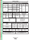
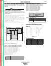
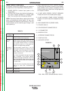
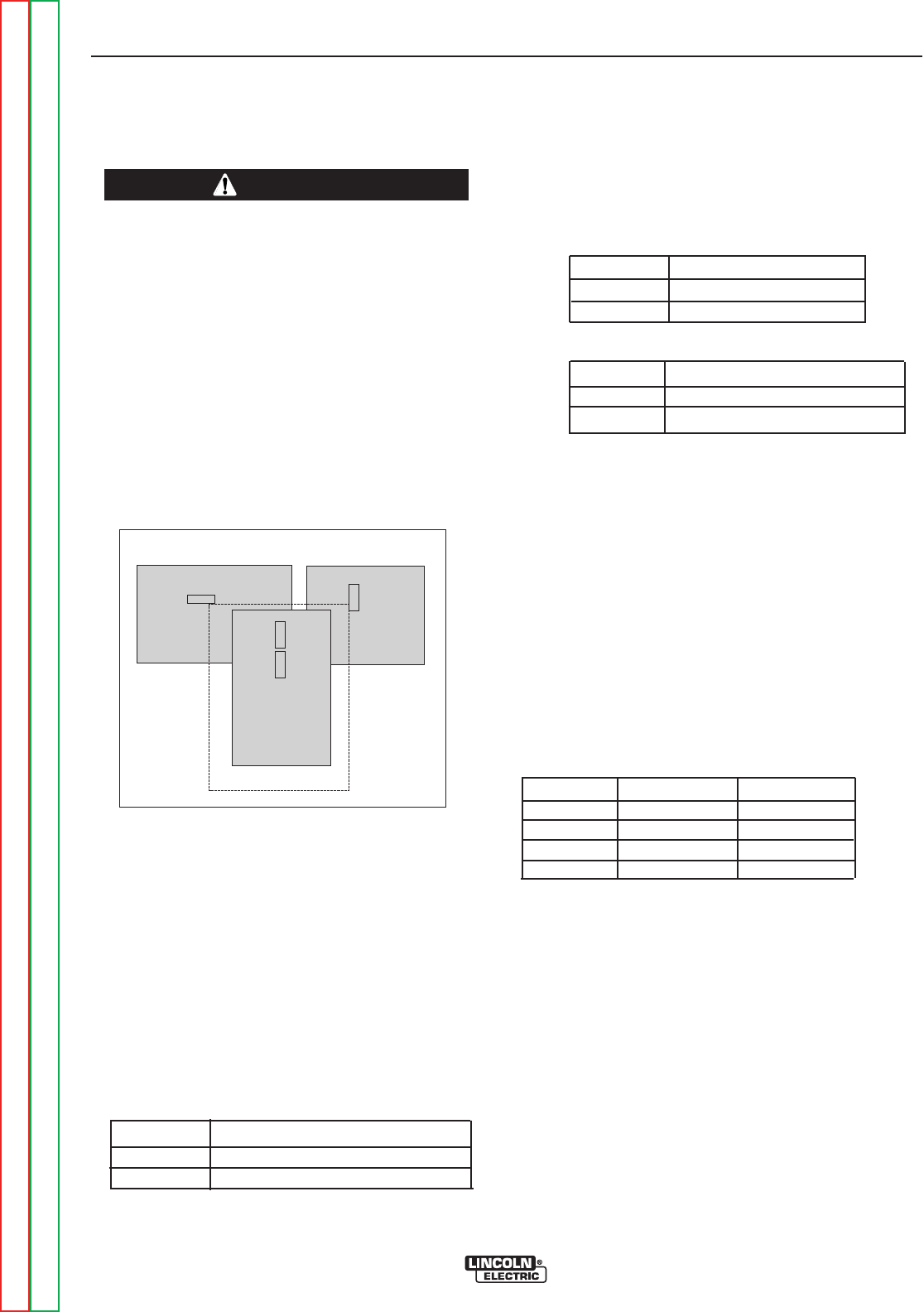
DIP Switch Settings and Locations
DIP switches on the P.C. Boards allow for custom con-
figuration of the Power Wave. To access the DIP
switches:
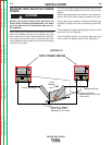
• Turn off power at the disconnect switch.
------------------------------------------------------------------------
• Remove the top four screws securing the front
access panel.
• Loosen, but do not completely remove, the bottom
two screws holding the access panel.
• Open the access panel, allowing the weight of the
panel to be carried by the bottom two screws. Make
sure to prevent the weight of the access panel from
hanging on the harness.
• Adjust the DIP switches as necessary.
• Replace the panel and screws, and restore power.
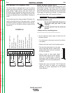
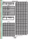
Control Board DIP Switch:
switch 1 = Object Instance LSB
1
(see table 3)
switch 2 = Object Instance
MSB
2
(see table 3)
switch 3 = Equipment Group 1 Select
switch 4 = Equipment Group 2 Select
switch 5 = Equipment Group 3 Select
switch 6 = Equipment Group 4 Select
switch 7 = reserved for future use
switch 8 = work sense lead
1
LEASE SIGNIFICANT BIT
2
MOST SIGNIFICANT BIT
switch 8
work sense lead
off work sense lead not connected
on work sense lead connected
Feed Head Board DIP Switch:
switch 1 = Object Instance LSB (see table 3)
switch 2 = Object Instance MSB (see table 3)
switch 3 = Equipment Group 1 Select
switch 4 = Equipment Group 2 Select
switch 5 = Equipment Group 3 Select
switch 6 = Equipment Group 4 Select
switch 7 = negative polarity switch
switch 7
electrode polarity
off positive (default)
on negative
switch 8 = high speed gear
switch 8
wire drive gear
off low speed gear (default)
on high speed gear
DeviceNET/Gateway Board DIP Switch:
Bank (S1)
:
switch 1 = Object Instance LSB (see table3)
switch 2 =
Object Instance MSB (see table 3)
switch 3 = Equipment Group 1 Select
switch 4 = Equipment Group 2 Select
switch 5 = Equipment Group 3 Select
switch 6 = Equipment Group 4 Select
switch 7 = Reserved for future use
switch 8 = Reserved for future use
TABLE 3
Object Instance
switch 2 switch 1 Instance
off off 0 (default)
off on 1
on off 2
on on 3
WARNING
DeviceNET/Gateway Board
Control Board
Feed Head Board
Right
Left