


CALIBRATION PROCEDURE (CONTINUED)
TROUBLESHOOTING & REPAIR
F-69 F-69
POWER WAVE 655/R
Return to Section TOC Return to Section TOC Return to Section TOC Return to Section TOC
Return to Master TOC Return to Master TOC Return to Master TOC Return to Master TOC
CALIBRATION PROCEDURE
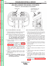
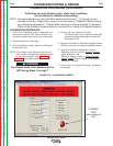
1. Once in the “Calibration” screen, make sure that
the machine output is OFF (light is BLACK) and
connect a resistive load bank to the output studs.
2. Set the load bank for 300 amps.
3. On the Calibration screen, select the “300 Amps”
Current Set Point.
NOTE: If the meters on the load bank are not certi-
fied, connect calibrated and traceable meters
to the machine output. (See Materials
Needed at the beginning of this section).
The Output Studs of the Machine will be
HOT during Steps 4 through 7
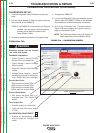
4. Click on the “Turn Output ON” button.
The BLACK light on the screen will flash RED
indicating that the weld output is turned ON.
(See Figure F.25).
5. Adjust the load bank to 300 Amps at approximately
32 Volts as read on the external calibrated meters.
6. Using the “Calibration Adjustment” buttons:
Adjust the current so that the external
ammeter
reads 300Amps +/-2A.
Adjust the voltage so that the “Output
Voltage”
display window reads the same as the external
voltmeter +/-.25volts.
7. Click on the “Turn Output Off” button. Calibration
is complete.
NOTE: Incorrect calibration can and will affect welding performance. It is strongly recom-
mended to use the “Diagnostics” screen to run and save a “Snapshot” before making
any calibration adjustments. This will allow returning to original settings if necessary.
(Refer to the Software Documentation for instructions on using the Snapshot feature).
FIGURE F.25 - CALIBRATION SCREEN
FLASHES
RED
when output is
ON.
WARNING
Calibration can only be done under ʻstatic loadʼ conditions.
Do not attempt to calibrate while welding.