


INSTALLATION
A-6 A-6
POWER WAVE 655/R
Return to Section TOC Return to Section TOC Return to Section TOC Return to Section TOC
Return to Master TOC Return to Master TOC Return to Master TOC Return to Master TOC
ELECTRODE AND WORK CABLE
CONNECTIONS
Connect a work lead of sufficient size and length (Per
Table 1) between the proper output terminal on the
power source and the work. Be sure the connection to
the work makes tight metal-to-metal electrical contact.
To avoid interference problems with other equipment
and to achieve the best possible operation, route all
cables directly to the work and wire feeder. Avoid
excessive lengths and do not coil excess cable.
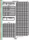
Minimum work and electrode cable sizes are as follows:
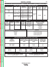
TABLE 1 (For cable length up to 100 ft, or 30 meters)
CURRENT (60% Duty Cycle) MINIMUM COPPER
400 Amps 2/0 (67mm2)
500 Amps 3/0 (85mm2)
600 Amps 3/0 (85mm2)
When using inverter type power sources like the
Power Waves, use the largest welding (electrode and
ground) cables that are practical. At least 2/0 copper
wire - even if the average output current would not nor-
mally require it. When pulsing, the pulse current can
reach very high levels. Voltage drops can become
excessive, leading to poor welding characteristics, if
undersized welding cables are used.
NOTE: K1796 coaxial welding cable is recommended
to reduce the cable inductance in long cable lengths.
This is especially important when Pulse welding up to
350 amps.
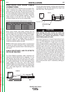
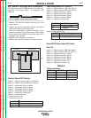
CABLE INDUCTANCE, AND ITS EFFECTS
ON PULSE WELDING
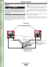
For Pulse Welding processes, cable inductance will
cause the welding performance to degrade. For the
total welding loop length less than 50ft.(15m), tradi-
tional welding cables may be used without any effects
on welding performance. For the total welding loop
length greater than 50ft.(15m), the K1796 Coaxial
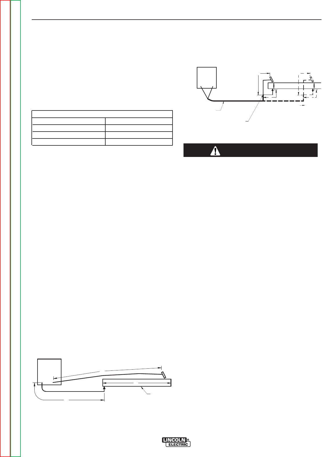
Welding Cables are recommended. The welding loop
length is defined as the total of electrode cable length
(A) + work cable length (B) + work length (C) (See
Figure A.3).
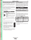
For long work piece lengths, a sliding ground should be
considered to keep the total welding loop length less
than 50ft.(15m). (See Figure A.4.)
When pulsing, the pulse current can reach very
high levels. Voltage drops can become excessive,
leading to poor welding characteristics, if under-
sized welding cables are used.
------------------------------------------------------------------------
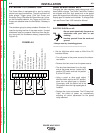
Most welding applications run with the electrode being posi-
tive (+). For those applications, connect one end of the elec-
trode cable to the positive (+) output stud on the power
source (located beneath the spring loaded output cover near
the bottom of the case front). Connect the other end of the
electrode cable to the wire drive feed plate using the stud,
lockwasher, and nut provided on the wire drive feed plate.
The electrode cable lug must be against the feed plate. Be
sure the connection to the feed plate makes tight metal-to-
metal electrical contact. The electrode cable should be sized
according to the specifications given in the work cable con-
nections section. Connect a work lead from the negative (-)
power source output stud to the work piece. The work piece
connection must be firm and secure, especially if pulse weld-
ing is planned. Excessive voltage drops caused by poor work
piece connections often result in unsatisfactory welding per-
formance.
CAUTION
B
A
C
FIGURE A.3
POWER
WAVE
WORK
A
C
B
POWER
W
AVE
FIGURE A.4
K
1796 COAXIAL CABLE
M
EASURE FROM END
OF OUTER JACKET OF
CABLE
C
A
B
W
ORK
SLIDING GROUND