


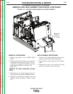
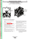
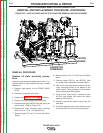
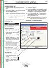
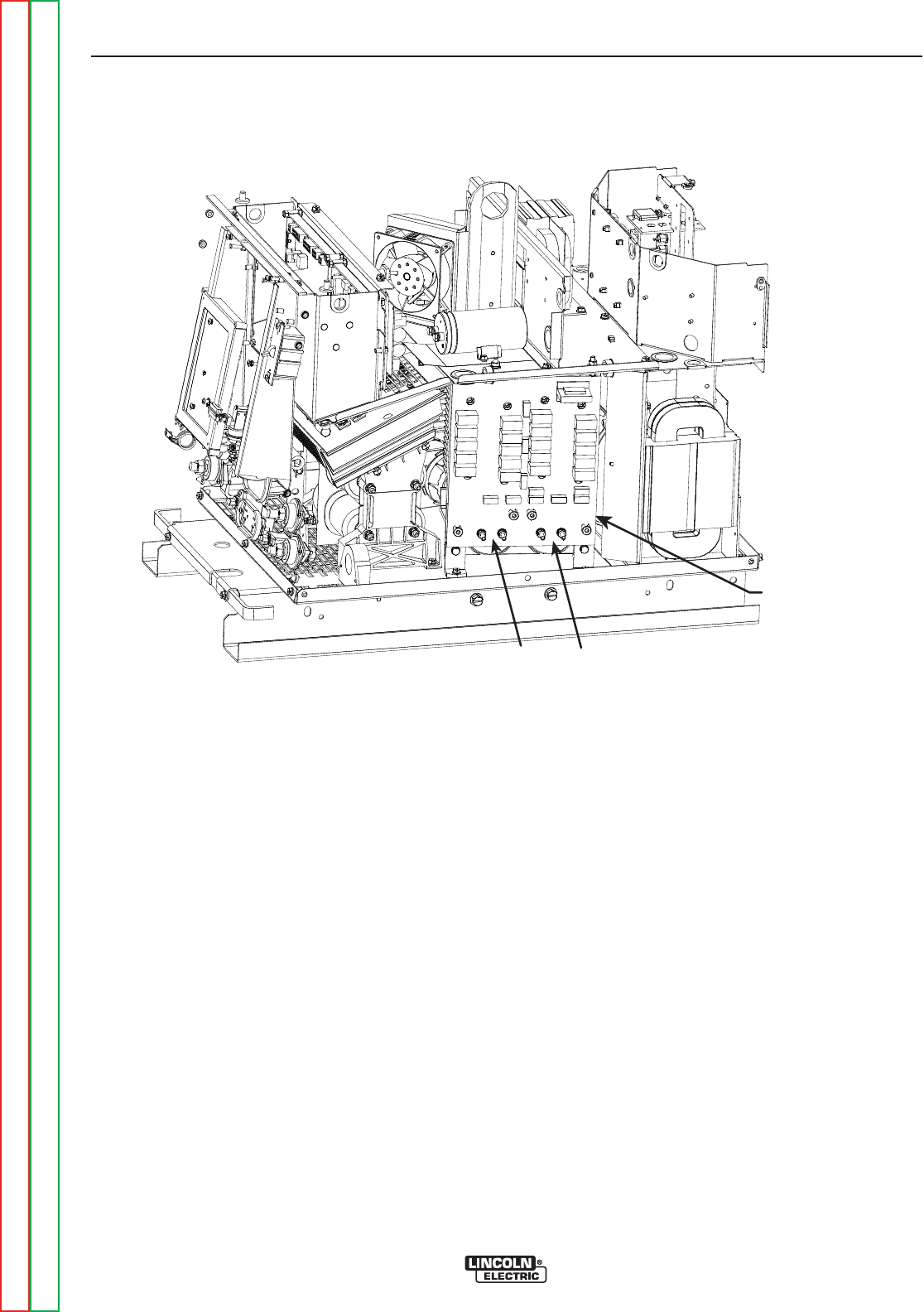
SWITCH
BOARD
CAPACITOR
TERMINALS
FIGURE F.23 – SWITCH BOARD AND FILTER CAPACITOR REMOVAL AND REPLACEMENT
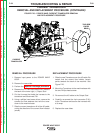
SWITCH BOARD AND FILTER CAPACITOR
REMOVAL AND REPLACEMENT PROCEDURE (CONTINUED)
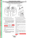
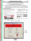
REMOVAL PROCEDURE
Observe all static electricity precau-
tions
.
Lead and plug references below use a slash (/) to
indicate machine right side/left side wire number
differences.
1. Remove input power to the POWER WAVE
655/R.
2. Remove the case top and sides.
3. Perform the Capacitor Discharge procedure.
4. Remove the high voltage protective shield.
5. Remove molex plug J40/J50 from the top of the
switch board. Refer to Figure F.22.
6. Remove the mylar insulating shield covering
leads 13/14 or 17/18. Cut the cable tie.
7. Remove leads 13/14 or 17/18 from the Switch
Board.
8. Remove leads 11/12 or 15/16 from the Switch
Board.
9. Remove leads 19C/D(+) and 20C/D(-) from
the switch board capacitor connection bolts.
10. With a slot head screwdriver, remove the two
nylon mounting screws at the bottom of the
switch board. Note placement of the shake-
proof washers and fiber spacers.
11. Using a 3/16” allen wrench, carefully remove
the four cap screws that mount the switch
board to the heat sink.
12. Carefully remove the switch board from the
heat sink.
13. If the filter capacitors are to be removed, care-
fully slide them out of the mounting bracket.
TROUBLESHOOTING & REPAIR
F-64 F-64
POWER WAVE 655/R
Return to Section TOC Return to Section TOC Return to Section TOC Return to Section TOC
Return to Master TOC Return to Master TOC Return to Master TOC Return to Master TOC