


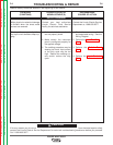
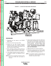
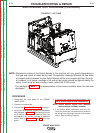
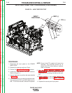
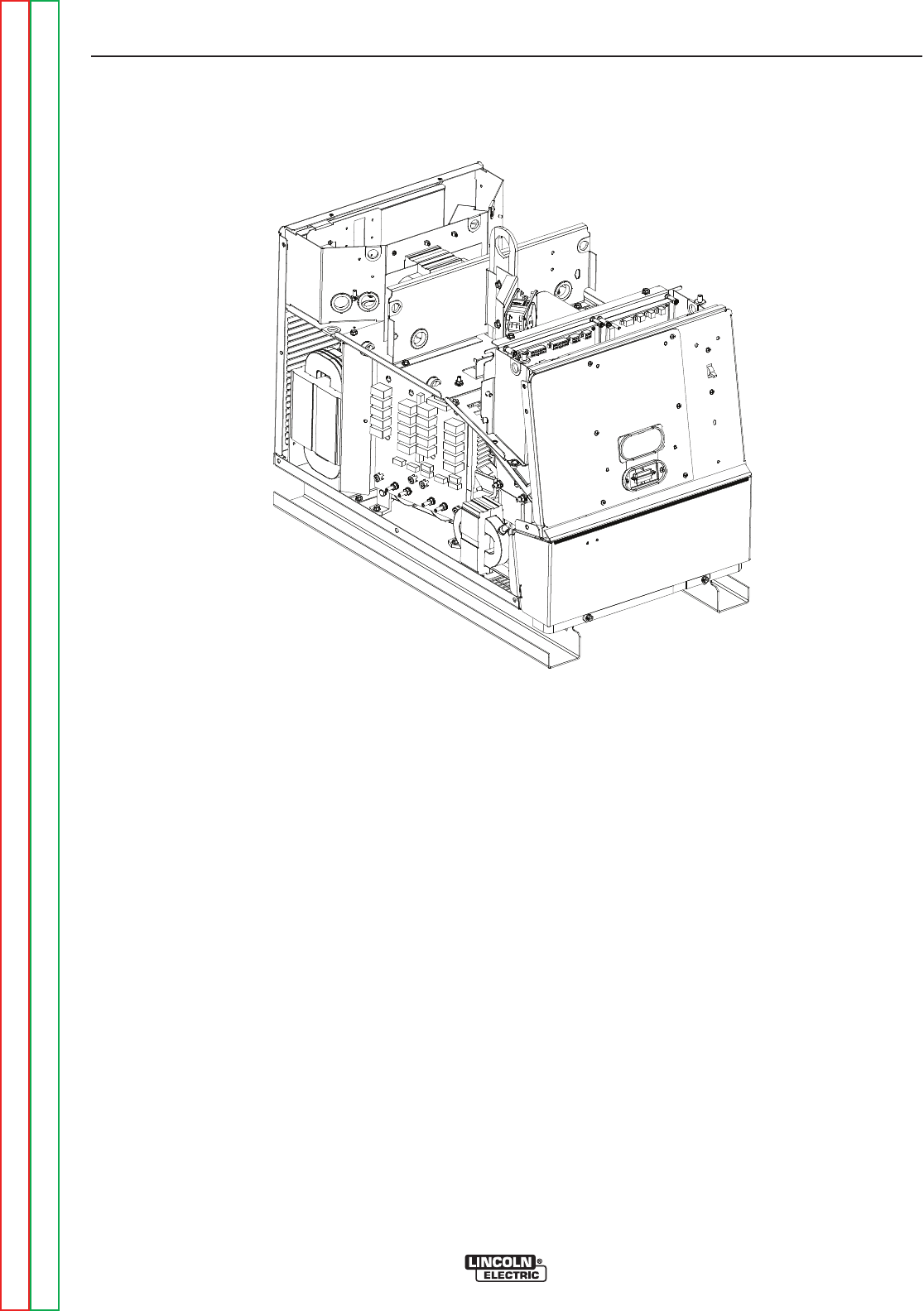
FIGURE F.2 – LEFT SIDE
SWITCH BOARD TEST PROCEDURE (CONTINUED)
PROCEDURE
1. Disconnect the input power to the POWER
WAVE 655/R.
2. Remove the case sides.
3. Perform the Capacitor Discharge Procedure.
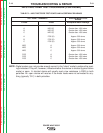
4 Using the volt-ohmmeter, perform the resistance
tests detailed in Table F.1. The readings should
all be similar. One or more readings that vary
considerably will usually indicate a defective
board. Refer to Figures F.2 and F.3 for the test
points
5. If any test fails replace the Switch Board. See
Switch Board Removal and Replacement.
NOTE: Switch boards should have Identical
base numbers and dash numbers.
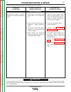
6. If the switch board resistance tests are OK,
check the molex pin connections and associat-
ed wiring from the switch boards to the control
board. See the Wiring Diagram.
TROUBLESHOOTING & REPAIR
F-14 F-14
POWER WAVE 655/R
Return to Section TOC Return to Section TOC Return to Section TOC Return to Section TOC
Return to Master TOC Return to Master TOC Return to Master TOC Return to Master TOC
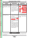
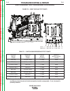
NOTE: Resistance checks of the Switch Boards in this machine will vary greatly depending on
the type and model of meter being used. Comparative readings between the two sides
of a board and/or between the two Switch Boards will be more meaningful than the actu-
al numbers. In all cases, readings of all sets of test points should be approximately the
same. If not using an ʻauto-rangingʼ meter, select the X1000 scale.
The readings in Table F.1 are representative of the meters available when this test was
developed.