


Return to Section TOC Return to Section TOC Return to Section TOC Return to Section TOC
Return to Master TOC Return to Master TOC Return to Master TOC Return to Master TOC
INSTALLATION
A-7 A-7
PRO-CUT 80
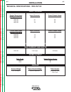
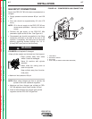
GAS INPUT CONNECTIONS
Supply the PRO-CUT 80 with clean compressed air or
nitrogen.
• Supply pressure must be between 80 psi and 150
psi.
• Flow rate should be approximately 6.0 cfm (170
I/min.).
NOTE: Oil in the air supply to the PRO-CUT 80 can
cause severe problems. Use only a clean air
supply.
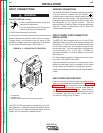
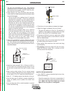
• Connect the gas supply to the PRO-CUT 80’s
pneumatic nipple at the air filter. See Figure A.3.
• Compressed gas should be supplied to the fitting
connection mounted on the filter at the rear of the
machine. If necessary, this fitting can be removed
allowing plumbing access through the 1/4 in.
(6.4mm) NPT input port on the filter body.
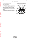
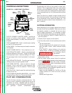
CYLINDER could explode if damaged.
• Keep cylinder upright and chained to a fixed support.
• Keep cylinder away from areas
where it could be damaged.
• Never lift machine with cylinder
attached.
• Never allow the cutting torch to
touch the cylinder.
• Keep cylinder away from live elec-
trical parts.
• Maximum inlet pressure 150 psi.
NOTE: When using nitrogen gas from a cylinder, the
cylinder must have a pressure regulator.
• Maximum psi from nitrogen gas cylinder to PRO-
CUT 80 regulator should never exceed 150 psi.
• Install a hose between the nitrogen gas cylinder
regulator and the PRO-CUT 80 gas inlet.
FIGURE A.3 - COMPRESSED GAS CONNECTION
1. CASE BACK
2. PNEUMATIC NIPPLE
3. AIR FILTER
4. FLEX TUBE (TO REGULATOR INSIDE MACHINE)
WARNING
1
2
3
4