


Return to Section TOC Return to Section TOC Return to Section TOC Return to Section TOC
Return to Master TOC Return to Master TOC Return to Master TOC Return to Master TOC
TROUBLESHOOTING & REPAIR
F-36 F-36
PRO-CUT 80
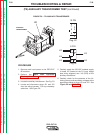
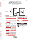
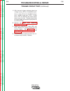
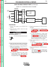
FIGURE F.12 - LOW VOLTAGE CIRCUIT DIAGRAM
#216
#219
15J40
10J40
6J2
9J2
#61
#62
#64
1J1
2J1
4J1
#54
#51
#56
#53
4J30
1J30
6J30
3J30
4
5
9
6
2
3
8
BROWN
BROWN
RED
RED
BLUE
WHITE
BLUE
H1
H2
H3
H4
H5
24VAC
12VAC
18VAC
18VAC
T2 AUXILIARY
TRANSFORMER
CONTROL BOARD
PLASMA
OUTPUT
BOARD
D
I
S
P
L
A
Y
B
O
A
R
D
+15VDC
+
TO
RECONNECT
LEAD "A"
TO H1
"C" TERMINAL
INPUT
RECTIFIER
J21
=17VDC
=28VDC
=+15VDC
=-15VDC
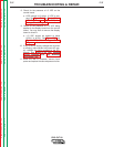
LOW VOLTAGE CIRCUIT TEST (continued)
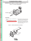
PROCEDURE
1. Remove input power to the PRO-CUT 80
machine.
2. Using the 5/16" nutdriver remove the case
wraparound cover.
ELECTRIC SHOCK can kill.
• Do not touch electrically hot parts.
3. Apply the correct input power to the machine
and carefully check for the following voltages.
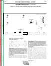
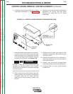
4. Check for the presence of approximately 32
VDC on the output board.
a. LED1 should be lit when 32 VDC is present.
See Figure F.13. See Output Board LED
Definitions and Figure F.12, Low Voltage
Circuit Diagram.
b. To verify the presence of 32 VDC, check
across capacitor C13. Make certain the
voltmeter probes make good contact with
the capacitor leads. See Figure F.13.
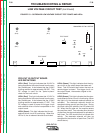
5. Check for the presence of 17 VDC on the out-
put board.
a. LED2 should be lit when 17 VDC is present.
See Figure F.13. See Output Board LED
Definitions and Figure F.12, Low Voltage
Circuit Diagram.
b. To verify the presence of 17 VDC, check
from plug J31 Pin-6 to diode D25 (anode).
See Figure F.13. Make certain the volt-
meter probes make good contact with pin-
6 and the diode anode lead. It will be nec-
essary to penetrate the silicon sealant.
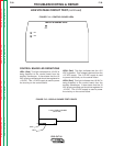
6. Check for the presence of +15 VDC on the
control board.
a. LED1 should be lit when +15 VDC is pre-
sent. See Figure F.13. See Control
Board LED Definitions and Figure F.12,
Low Voltage Circuit Diagram.
7. Check for the presence of -15 VDC on the con-
trol board.
a. LED3 should be lit when -15 VDC is pre-
sent. See Figure F.13. See Control Board
LED Definitions and Figure F.12, Low
Voltage Circuit Diagram.
WARNING
17 VDC
32 VDC