


TROUBLESHOOTING & REPAIR
F-55 F-55
PRO-CUT 80
Return to Section TOC Return to Section TOC Return to Section TOC Return to Section TOC
Return to Master TOC Return to Master TOC Return to Master TOC Return to Master TOC
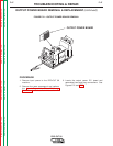
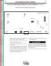
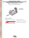
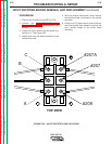
FIGURE F.25 – INPUT RECTIFIER LEAD LOCATIONS
#207A
#207
#209A
B
C
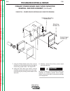
INPUT RECTIFIER BRIDGE REMOVAL AND REPLACEMENT (continued)
PROCEDURE
1. Remove input power to the PRO-CUT 80.
2. Perform the Input Filter Capacitor
Discharge Procedure detailed earlier in this
section.
3. Locate the input rectifier and the leads con-
nected to it. See Figure F.25.
4. Identify and mark the leads connected to the
rectifier terminals.
5. With the phillips head screw driver, remove
the lead terminals connected to the rectifier
terminals.
6. Using the 3/16” allen wrench, remove the two
cap head screws and washers mounting the
input rectifier bridge to the center panel
assembly.
TOP VIEW