


Return to Section TOC Return to Section TOC Return to Section TOC Return to Section TOC
Return to Master TOC Return to Master TOC Return to Master TOC Return to Master TOC
TROUBLESHOOTING & REPAIR
F-21 F-21
PRO-CUT 80
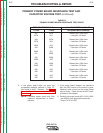
OUTPUT POWER BOARD RESISTANCE TEST (continued)
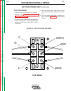
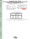
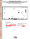
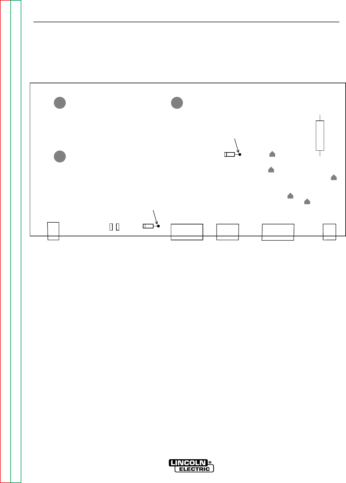
FIGURE F.4 – OUTPUT POWER BOARD LEAD LOCATIONS
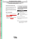
TEST PROCEDURE
1. Remove input power to the PRO-CUT 80
machine.
2. Perform the Input Filter Capacitor
Discharge Procedure detailed earlier in this
section.
3. Remove the torch assembly from the
machine.
4. Carefully remove leads X4, X2, B21, X20, X40
and plugs J33 and J32 from the output
power board. See Figure F.4.
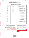
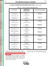
5. Using the analog ohmmeter, perform the
resistance checks per Table F.4.
G3439 PRO-CUT 80 OUTPUT
LED1
LED2
D29
LED4
LED3
LED5
J33 J31 J34 J32 J30
X20
X40
X4 X2
(B12) (B11)
(B21)
TEST POINT
+
C13
D25
TEST POINT