


Return to Section TOC Return to Section TOC Return to Section TOC Return to Section TOC
Return to Master TOC Return to Master TOC Return to Master TOC Return to Master TOC
TROUBLESHOOTING & REPAIR
F-24 F-24
PRO-CUT 80
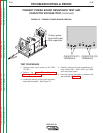
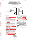
TORCH CONTINUITY AND SOLENOID TEST (continued)
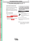
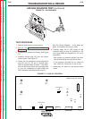
TEST PROCEDURE
1. Remove input power to the PRO-CUT 80
machine.
2. Remove the torch assembly from the
machine.
3. Using the ohmmeter, check the torch resis-
tances per Table F.5.
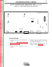
NOTE: Take the “Pin” test point measurements
at the machine end of the torch assem-
bly. See Figure F.5.
4. If any of the resistance checks are not cor-
rect, the torch assembly may be faulty.
Repair or replace.
5. Carefully apply the 12 VDC supply to the
electrode solenoid. (positive to Pin 2 and
negative to Pin 3). The electrode solenoid
should activate. Listen for the solenoid
action in the torch handle. If the solenoid
does not activate, it may be faulty. Replace.
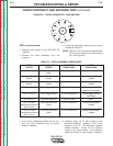
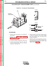
FIGURE F.5 - TORCH CONNECTOR - MACHINE END
1
2
3
4
5
6
7
8
9
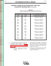
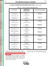
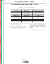
TABLE F.5 - TORCH ASSEMBLY RESISTANCES
TEST CIRCUIT(S) BEING EXPECTED TEST
POINTS TESTED RESISTANCE CONDITIONS
Pin 7 to Pin 8 Parallel pilot arc 1.5 ohms maximum None
leads
Pin 7 to Torch One pilot arc lead to 1.0 ohm maximum Torch consumables
Nozzle nozzle in place
Pin 8 to Torch One pilot arc lead to 1.0 ohm maximum Torch consumables
Nozzle nozzle in place
Pin 1 to Pin 9 Torch trigger circuit 100K ohms minimum Torch trigger NOT
pulled (not activated)
Pin 1 to Pin 9 Torch trigger circuit 1.0 ohm maximum Torch trigger pulled
(activated)
Pin 2 to Pin 3 Electrode Solenoid 45 to 55 ohms None
Pin 7 to Torch Pilot and Electrode 1.0 ohm maximum Torch consumables
Electrode at machine circuit in place
end of torch
Pin 8 to Torch Pilot and Electrode 1.0 ohm maximum Torch consumables
Electrode at machine circuit in place
end of torch