


Return to Section TOC Return to Section TOC Return to Section TOC Return to Section TOC
Return to Master TOC Return to Master TOC Return to Master TOC Return to Master TOC
TROUBLESHOOTING & REPAIR
F-16 F-16
PRO-CUT 80
PRIMARY POWER BOARD RESISTANCE TEST AND
CAPACITOR VOLTAGE TEST (continued)
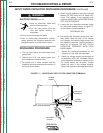
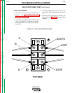
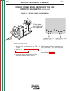
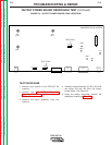
FIGURE F.3 – PRIMARY POWER BOARD REMOVAL
+
+
CAPACITOR (C2)
TERMINALS
CAPACITOR (C1)
TERMINALS
PRO-CUT 80 POWER G3440 - 1
203 206
207 202
201
204
205
208
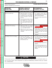
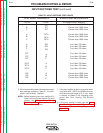
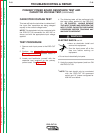
TEST PROCEDURE
1. Remove main input power to the PRO-
CUT 80.
2. Perform the Input Filter Capacitor
Discharge Procedure detailed earlier in
this section.
3. Locate the primary power board and asso-
ciated lead locations. See Figure F.3.
4. Carefully remove the main transformer pri-
mary leads #201, #204, #205 and #208
from the power board.
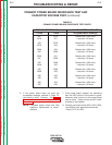
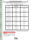
5. Use the analog ohmmeter to perform the
test outlined in Table F.2.
Primary power
board with input
filter capacitors