


TROUBLESHOOTING & REPAIR
F-56 F-56
PRO-CUT 80
Return to Section TOC Return to Section TOC Return to Section TOC Return to Section TOC
Return to Master TOC Return to Master TOC Return to Master TOC Return to Master TOC
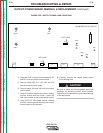
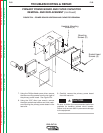
INPUT RECTIFIER BRIDGE REMOVAL AND REPLACEMENT (continued)
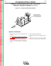
7. Carefully remove the input rectifier bridge.
8. When installing a new input rectifier apply a
thin coating of Penetrox A-13 Heat Sink
Compound (Lincoln E2529) to the mating
surfaces. Torque the mounting cap screws
and nuts to 44 in-lbs.
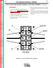
9.
Reconnect the 10 leads to the correct ter-
minals and torque the phillips head screws
to 31 in-lbs.
10. Apply Dow Corning 738 Insulating Com-
pound to all six screw heads and termi-
nals. The heavy input lead terminals
should be against the rectifier terminals.
11. Assemble case wrap-around cover.