


Return to Section TOC Return to Section TOC Return to Section TOC Return to Section TOC
Return to Master TOC Return to Master TOC Return to Master TOC Return to Master TOC
TROUBLESHOOTING & REPAIR
F-28 F-28
PRO-CUT 80
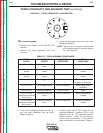
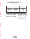
(T2) AUXILIARY TRANSFORMER TEST (continued)
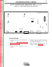
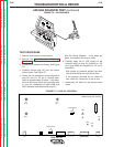
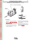
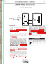
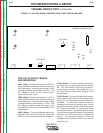
FIGURE F.8 – T2 AUXILIARY TRANSFORMER
PROCEDURE
1. Remove main input power to the PRO-CUT
80 machine.
2. Perform the Input Filter Capacitor
Discharge Procedure detailed earlier in this
section.
3. Locate the auxiliary transformer. See Fig. F.8
4. Locate and disconnect plugs J21 and J22
from the wiring harness. Cut any necessary
cable ties. See Figure F.8.
5. Carefully apply the 230 VAC isolated supply
to leads H1 located at the D1 input bridge
(see wiring diagram) and H3 (2J22) of the
auxiliary transformer.
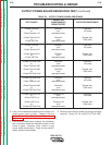
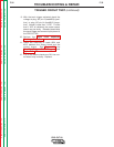
6. Carefully check for the presence of the fol-
lowing primary and secondary voltages at the
appropriate leads at plugs J21 and J22. See
Figure F.8 and Table F.6..
6
1
7
2
8
3
9
4
5
10 PIN
Plug J21
8 PIN
5
1
2
7
8
4
Plug 22
D1
AUXILIARY
TRANSFORMER
H3
H6H5
H4
H2