


Return to Section TOC Return to Section TOC Return to Section TOC Return to Section TOC
Return to Master TOC Return to Master TOC Return to Master TOC Return to Master TOC
TROUBLESHOOTING & REPAIR
F-11 F-11
PRO-CUT 80
ELECTRIC SHOCK can kill.
• Have an electrician install and
service this equipment.
• Turn the input power off at the
fuse box before working on
equipment.
• Do not touch electrically hot parts.
• Prior to performing preventative mainte-
nance, perform the following capacitor dis-
charge procedure to avoid electric shock.
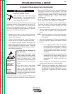
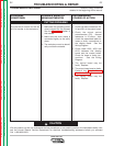
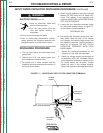
DISCHARGE PROCEDURE
1. Turn off input power and disconnect input
power lines.
2. Remove the 5/16" hex head screws from
the wraparound machine cover.
3. Be careful not to make contact with the
capacitor terminals located at the bottom of
the Input Power Board.
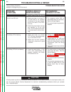
4. Obtain a high resistance and high wattage
resistor (25-1000 ohms and 25 watts mini-
mum). This resistor is not supplied with
machine. NEVER USE A SHORTING STRAP
FOR THIS PROCEDURE.
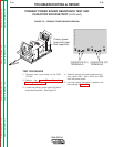
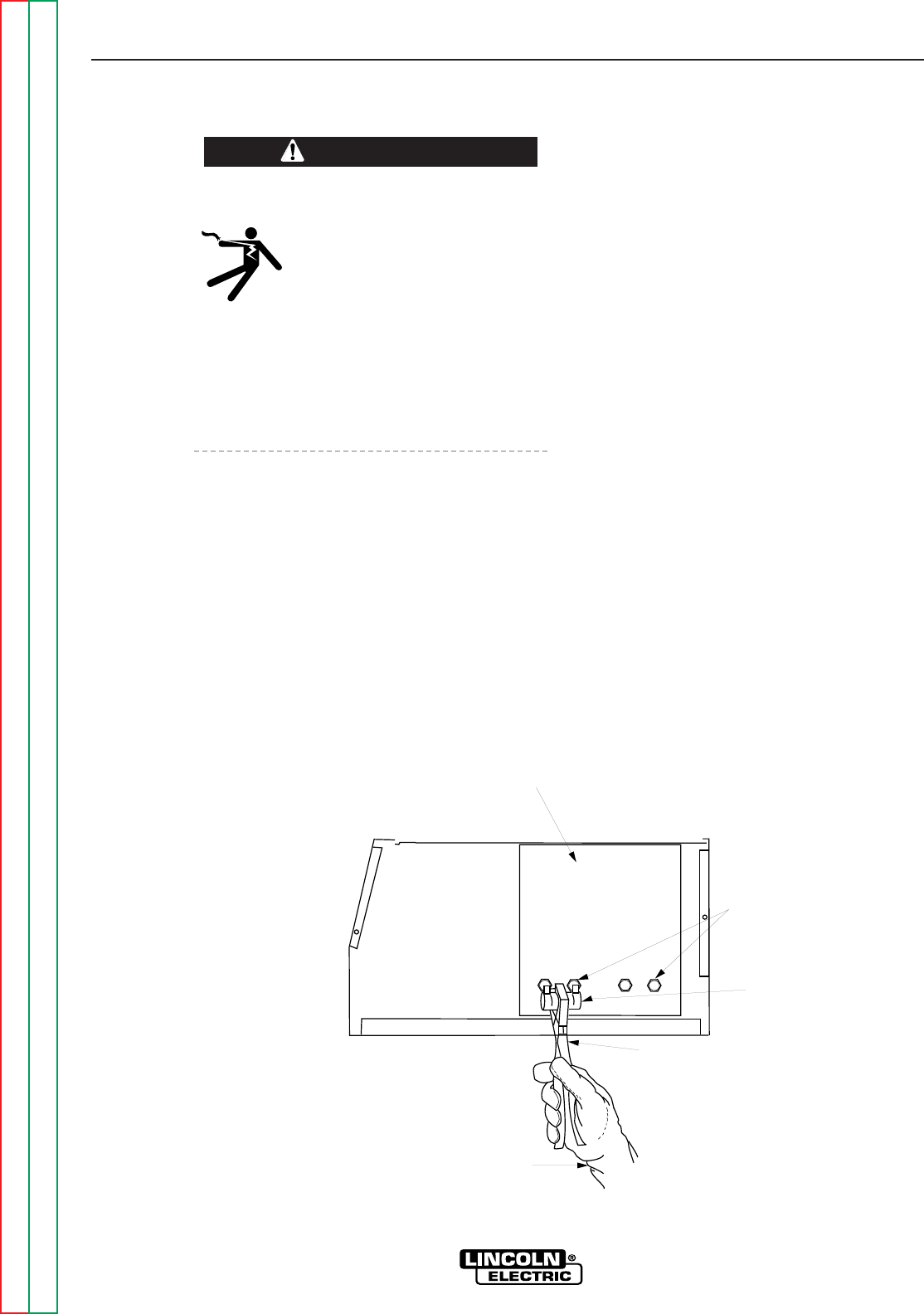
5. Locate the four capacitor terminals (large
hex head cap screws) shown in Figure F.1.
At the bottom of the PowerBoard
(203,206)(207,202)
6. Use electrically insulated gloves and insu-
lated pliers. Hold the body of the resistor
and connect the resistor leads across the
two capacitor terminals. Hold the resistor in
place for 10 seconds. DO NOT TOUCH
CAPACITOR TERMINALS WITH YOUR
BARE HANDS.
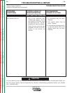
7. Repeat the discharge procedure for the
capacitor on the other two terminals.
8. Check the voltage across the terminals of
all capacitors with a DC voltmeter. Polarity
of the capacitor terminals is marked on the
PC board above the terminals. Voltage
should be zero. If any voltage remains,
repeat this capacitor discharge procedure.
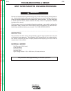
WARNING
CAPACITOR
TERMINALS
POWER
RESISTOR
POWER
BOARD
RIGHT SIDE OF MACHINE
INSULATED
GLOVES
INSULATED
PLIERS
FIGURE F.1 – LOCATION OF INPUT FILTER CAPACITOR TERMINALS
INPUT FILTER CAPACITOR DISCHARGE PROCEDURE (continued)