


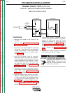
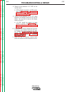

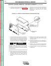

8. Check for the presence of +5 VDC on the
control board.
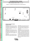
a. LED2 should be lit when +5 VDC is pre-
sent. See Figure F.14. See Control Board
LED Definitions and Figure F.12, Low
Voltage Circuit Diagram.
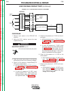
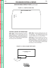
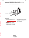
9. Check for the presence of +15 VDC being
applied to the display board from the control
board. You may have to remove the display
board to check it.
a. +15 VDC should be present at leads
#216(+) to #219(-). See Figure F.15 and
Figure F.12, Low Voltage Circuit
Diagram.
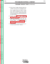
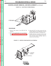
10. If any of the DC supply voltages are incorrect
or missing, make certain the correct AC sup-
ply voltages are being applied to the P.C.
boards. See Figure F.12, Low Voltage
Circuit Diagram and (T2) Auxiliary
Transformer Test.
11.
When the test is complete, remove input
power and replace the case wraparound cover.
TROUBLESHOOTING & REPAIR
F-37 F-37
PRO-CUT 80
Return to Section TOC Return to Section TOC Return to Section TOC Return to Section TOC
Return to Master TOC Return to Master TOC Return to Master TOC Return to Master TOC