


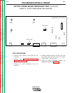

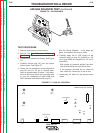
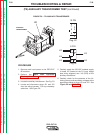
6. If any of the resistance checks are not correct, the
output power board is faulty. Replace. See the
Output Power Board Removal and Replacement
Procedure.
7. If the output power board “passes” the resistance
test, the power diode and transistor portion of the
board is good. However, other circuits on the
power board may be faulty. These circuits are NOT
readily tested or serviceable.
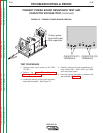
8. Carefully reconnect the leads and plugs previously
removed. Torque X2, X4, and B21 to 75 IN. LBS.
TROUBLESHOOTING & REPAIR
F-22 F-22
PRO-CUT 80
Return to Section TOC Return to Section TOC Return to Section TOC Return to Section TOC
Return to Master TOC Return to Master TOC Return to Master TOC Return to Master TOC
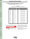
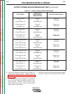
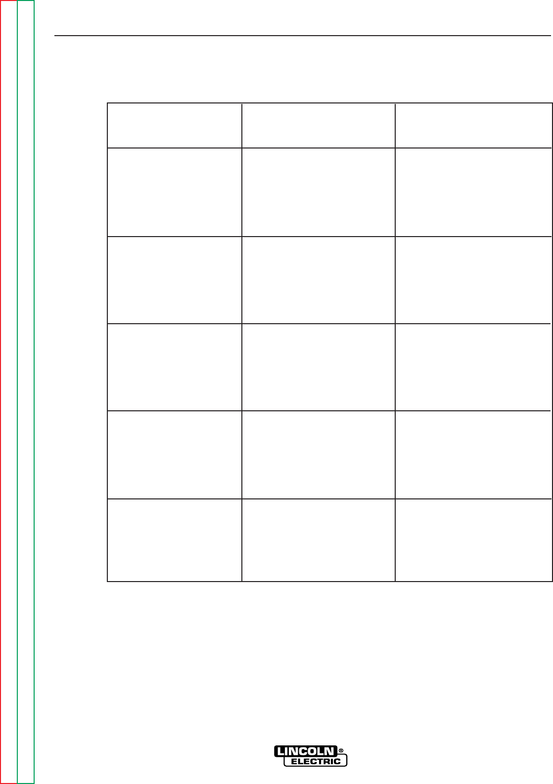
TABLE F.4 - OUTPUT POWER BOARD RESISTANCE
CIRCUIT OR
TEST POINTS COMPONENT(S) EXPECTED RESISTANCE
BEING TESTED
+Probe J33-Pin4 Diode A1 Less than
to and 100 ohms
–Probe Terminal X2 associated trace
+Probe Terminal X2 Diode A1 Greater than
to and 1000 ohms
–Probe J33-Pin4 associated trace
+Probe J33-Pin4 Diode A1 Less than
to and 100 ohms
–Probe Terminal X4 associated trace
+Probe Terminal X4 Diode A1 Greater than
to and 1000 ohms
–Probe J33-Pin4 associated trace
+Probe D29 Test Point Diode A2 Less than
to and 100 ohms
–Probe Terminal X20 associated trace
+Probe Terminal X20 Diode A2 Greater than
to and 1000 ohms
–Probe D29 Test Point associated trace
+Probe D29 Test Point Diode A2 Less than
to and 100 ohms
-Probe Terminal X40 associated trace
+Probe Terminal X40 Diode A2 Greater than
to and 1000 ohms
–Probe D29 Test Point associated trace
+Probe D29 Test Point Transistor A2 Less than
to and 100 ohms
–Probe J32-Pin14 associated trace
+Probe J32-Pin14 Transistor A2 Greater than
to and 1000 ohms
–Probe D29 Test Point associated trace
OUTPUT POWER BOARD RESISTANCE TEST (continued)