


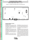
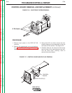
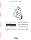
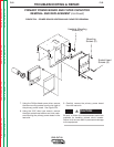
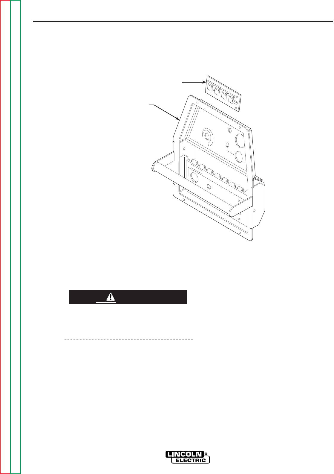
5. Locate the display P.C. board and the one
plug connected to it. See Figure F.20.
6. Gently remove the display P.C. board from
the three mounting pins.
Be sure to follow the recommended static-free
methods for handling printed circuit boards.
Failure to do so can result in permanent damage
to the equipment.
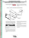
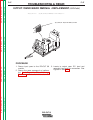
7. Depress the locking tab and remove the plug
connector from the display board.
8. When replacing the display board, carefully
connect the plug into the board. Make cer-
tain the plug is secure and the locking tab is
in place.
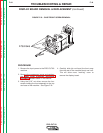
9. Align the display board with the three
mounting pins and slide the display board
into place.
10. Carefully reposition the front assembly in
place and install the four mounting screws
previously removed.
11. Inspect, clear and secure all leads in prepa-
ration for the case wraparound reassembly.
12. Using the 5/16” nut driver, install the case
wraparound.
Return to Section TOC Return to Section TOC Return to Section TOC Return to Section TOC
Return to Master TOC Return to Master TOC Return to Master TOC Return to Master TOC
TROUBLESHOOTING & REPAIR
F-45 F-45
PRO-CUT 80
FIGURE F.20 – DISPLAY BOARD REMOVAL
CASE FRONT
DISPLAY BOARD
DISPLAY BOARD REMOVAL & REPLACEMENT (continued)
CAUTION