


Return to Section TOC Return to Section TOC Return to Section TOC Return to Section TOC
Return to Master TOC Return to Master TOC Return to Master TOC Return to Master TOC
TROUBLESHOOTING & REPAIR
F-13 F-13
PRO-CUT 80
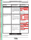
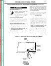
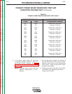
INPUT RECTIFIER TEST (continued)
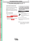
TEST PROCEDURE
1. Remove main input power to the machine.
2. Perform the Input Filter Capacitor
Discharge Procedure detailed earlier in
this section.
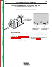
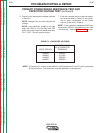
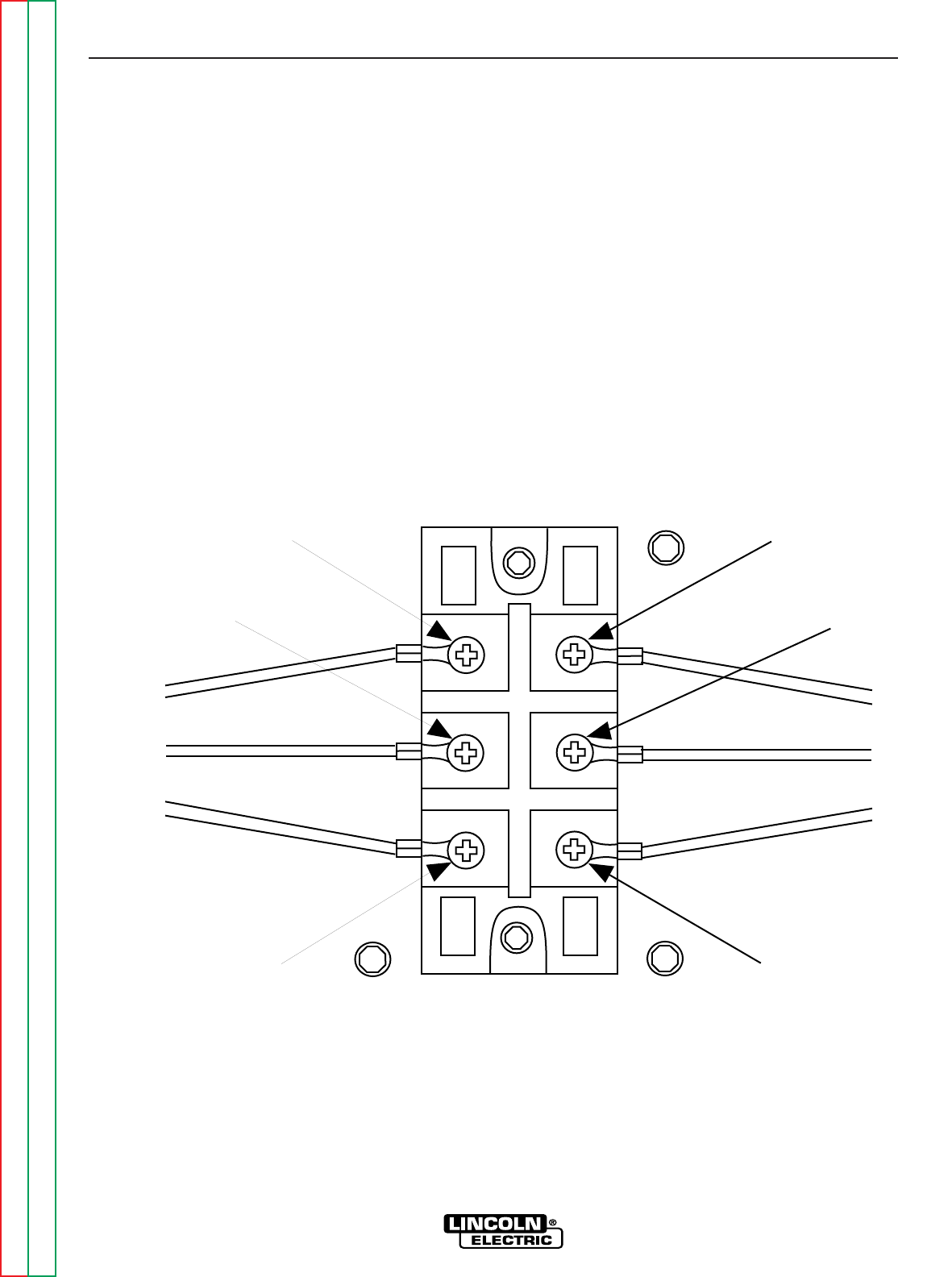
3. Locate the input rectifier (D1) and lead loca-
tions. See Figure F.2. Carefully remove the
silicone sealant from leads #207, #207A,
and #209.
4. With the phillips head screw driver, remove
leads #207, 207A and #209 from the rectifi-
er.
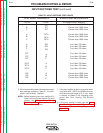
5. Use the analog ohmmeter to perform the
tests detailed in Table F.1. See the Wiring
Diagram.
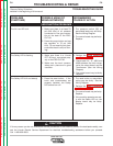
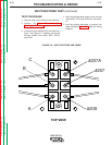
FIGURE F.2 – INPUT RECTIFIER AND LEADS
#207A
#207
#209A
B
C
TOP VIEW