


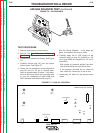
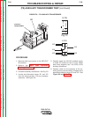
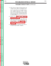
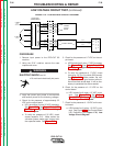
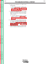

9. With the torch trigger activated check the
voltage at plug J32 pin-3 (lead#354) (posi-
tive) to plug J32 pin-14 (lead#312) (nega-
tive). Normal is less than 1 VDC. If more
than 1 VDC is indicated, the power output
board may be faulty. Release (deactivate)
the torch trigger and remove input power to
the PRO-CUT 80.
10. Perform the Input Filter Capacitor
Discharge Procedure.
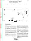
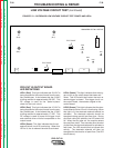
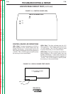
11. Check the continuity of leads #354 and
#312 between the output board and the
control board. See Figure F.9, the
Simplified Trigger Circuit Diagram, and
Figure F.10.
12. If all of the above checks are OK, the con-
trol board may be faulty. Replace.
TROUBLESHOOTING & REPAIR
F-32 F-32
PRO-CUT 80
Return to Section TOC Return to Section TOC Return to Section TOC Return to Section TOC
Return to Master TOC Return to Master TOC Return to Master TOC Return to Master TOC
TRIGGER CIRCUIT TEST (continued)