


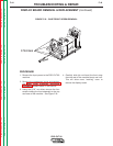
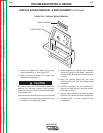

REPLACEMENT PROCEDURE
1. Apply a thin coating of Penetrox A-13
Electrical Joint Compound to the mating sur-
faces of the output power board and the heat
sink. Make sure the surfaces are clean. Do
not allow the compound to get into the
threaded holes or on the screw threads.
Be sure to follow the recommended static-free
methods for handling printed circuit boards.
Failure to do so can result in permanent damage
to the equipment.
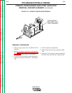
2. Mount the output power board to the heat
sink and pre-torque the four socket head
screws to 25 inch-pounds.
3. Finish tightening the four screws to 40-48
inch-pounds.
4. Replace the four phillips head screws previ-
ously removed.
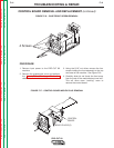
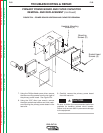
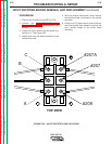
5. Replace leads X20 and X40.
6. Replace plugs J30, J31, J32, J33, and J34.
7. Replace leads X4 and X2, then torque to 75
IN. LBS.
8. Replace lead B21 and torque it to 75 IN. LBS.
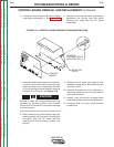
9. Clear and secure all leads and replace the
wraparound cover.
TROUBLESHOOTING & REPAIR
F-49 F-49
PRO-CUT 80
Return to Section TOC Return to Section TOC Return to Section TOC Return to Section TOC
Return to Master TOC Return to Master TOC Return to Master TOC Return to Master TOC
CAUTION