


Return to Section TOC Return to Section TOC Return to Section TOC Return to Section TOC
Return to Master TOC Return to Master TOC Return to Master TOC Return to Master TOC
TROUBLESHOOTING & REPAIR
F-26 F-26
PRO-CUT 80
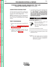
AIR/GAS SOLENOID TEST (continued)
TEST PROCEDURE
1. Remove input power to the machine.
2. Perform the Input Capacitor Discharge
Procedure detailed earlier in this section.
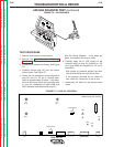
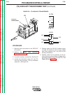
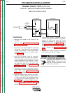
3. Locate the air solenoid and leads. See Figure
F.6.
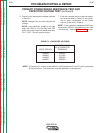
4. Carefully remove plug J31 from the output
power board. See Figure F.7.
5. Check the coil resistance of the solenoid at
plug J31 pin-6 to J31 pin-5. Normal resis-
tance is approximately 20 ohms. If the resis-
tance is abnormal, check the continuity (zero
or very low resistance) of leads #366 and
#361 between the solenoid and plug J31.
See the Wiring Diagram. If the leads are
good, the solenoid coil may be faulty.
6. Carefully apply the 12 VDC supply to the
solenoid leads at plug J31 (positive to J31
pin-6 lead #366 and negative to J31 pin-5
lead #361).
With proper air pressure applied, the sole-
noid should activate and air should flow.
If the solenoid activates but air does not
flow, check for a restriction in the air line.
7. Install plug J31 back into the output power
board.
FIGURE F.6 – AIR SOLENOID
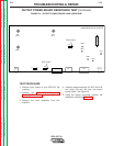
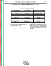
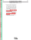
G3439 PRO-CUT 80 OUTPUT
LED1
LED2
D29
LED4
LED3
LED5
J33 J31 J34 J32 J30
X20
X40
X4 X2
(B12) (B11)
(B21)
TEST POINT
+
C13
D25
TEST POINT
FIGURE F.7 – PLUG J31 LOCATION