


TROUBLESHOOTING & REPAIR
F-48 F-48
PRO-CUT 80
Return to Section TOC Return to Section TOC Return to Section TOC Return to Section TOC
Return to Master TOC Return to Master TOC Return to Master TOC Return to Master TOC
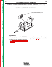
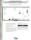
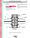
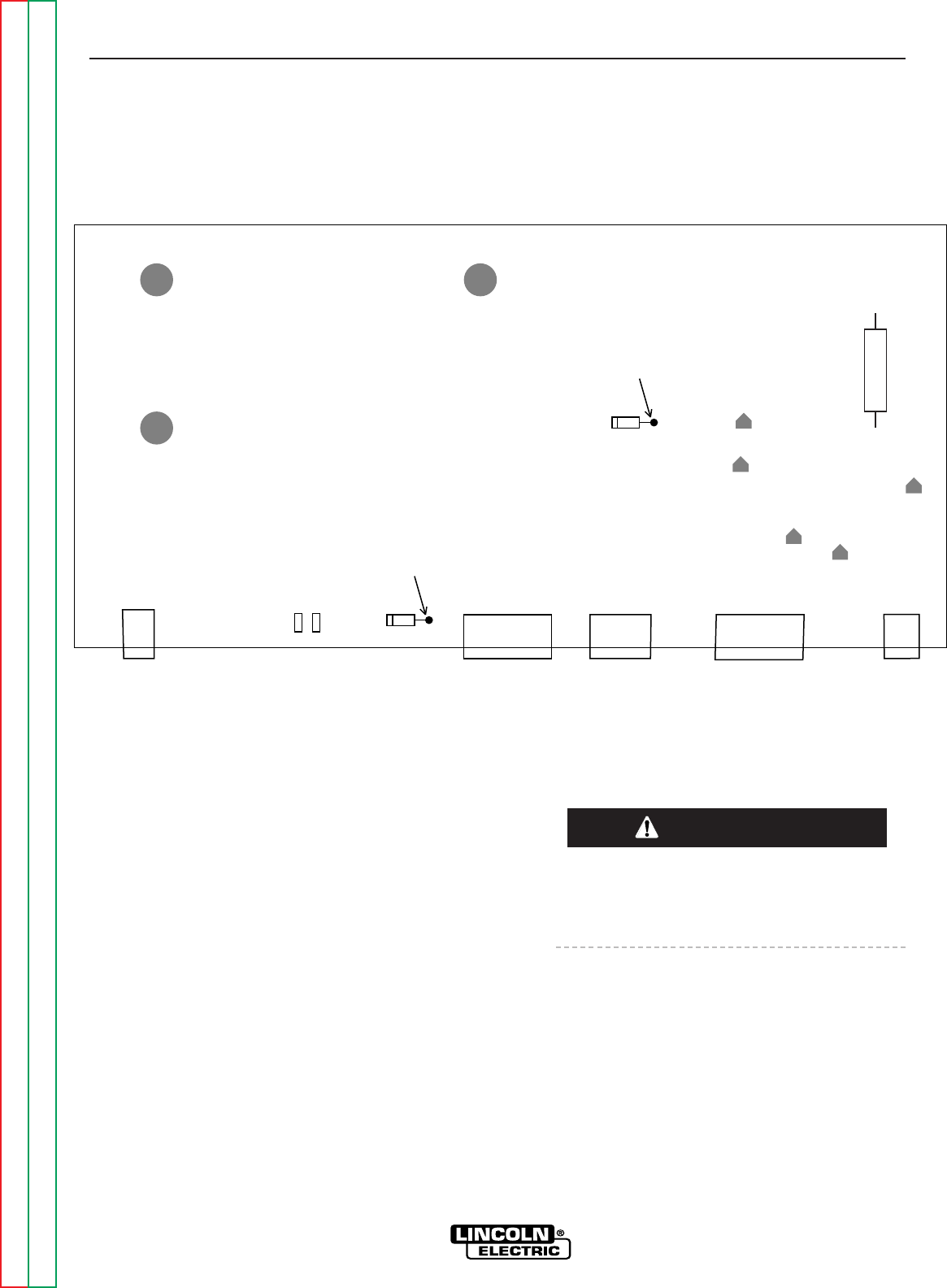
FIGURE F.22 – OUTPUT BOARD LEAD LOCATIONS
G3439 PRO-CUT 80 OUTPUT
LED1
LED2
D29
LED4
LED3
LED5
J33 J31 J34 J32 J30
X20
X40
X4 X2
(B12) (B11)
(B21)
TEST POINT
+
C13
D25
TEST POINT
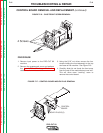
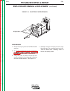
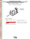
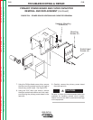
OUTPUT POWER BOARD REMOVAL & REPLACEMENT (continued)
4. Using the 7/16” wrench, remove leads X4, X2
and B21 from the output power board.
5. Remove plugs J30, J31, J32, J33, and J34
from the output power board.
6. Remove leads X20 and X40 from the output
power board.
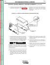
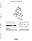
7. Using the phillips head screw driver, remove
the four screws from the lower + upper left
and right corners of the output power board.
8. Using the 3/16” allen head wrench, remove
the four socket screws mounting the output
power board to the heat sink.
9. Carefully remove the output power board
from the heat sink.
Be sure to follow the recommended static-free
methods for handling printed circuit boards.
Failure to do so can result in permanent damage
to the equipment.
CAUTION