


Return to Section TOC Return to Section TOC Return to Section TOC Return to Section TOC
Return to Master TOC Return to Master TOC Return to Master TOC Return to Master TOC
TROUBLESHOOTING & REPAIR
F-19 F-19
PRO-CUT 80
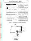
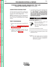
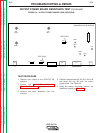
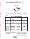
6. Check for the appropriate voltages outlined
in Table F.3.
NOTE: Voltages may vary with the input line
voltage.
NOTE: If the capacitor voltage is too high
(over 400 VDC) or too low (less than 220
VDC) the control board will deactivate relay
CR1 + CR2. This will prevent output.
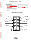
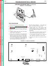
7. If the test voltages do not meet the expect-
ed values as listed in Table F.3, the capaci-
tors or other components on the power
board may be faulty. Replace.
NOTE: If the capacitor voltages are NOT bal-
anced within 20 VDC, the capacitors may need
“conditioning.” See the Maintenance section.
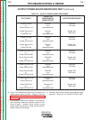
PRIMARY POWER BOARD RESISTANCE TEST AND
CAPACITOR VOLTAGE TEST (continued)
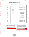
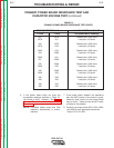
EXPECTED VOLTS
DC AT CAPACITOR
INPUT APPLIED TERMINALS
460VAC 325VDC
440VAC 311VDC
415VAC 293VDC
380VAC 269VDC
TABLE F.3 - CAPACITOR VOLTAGES
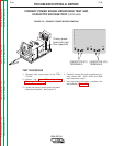
NOTE: If Capacitor C1 is found to be defective, both Capacitors C1 and C2 must be replaced
at the same time. The capacitors must be replaced in matched sets.