


Return to Section TOC Return to Section TOC Return to Section TOC Return to Section TOC
Return to Master TOC Return to Master TOC Return to Master TOC Return to Master TOC
TROUBLESHOOTING & REPAIR
F-31 F-31
PRO-CUT 80
TRIGGER CIRCUIT TEST (continued)
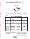
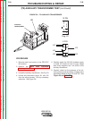
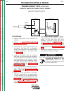
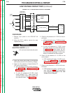
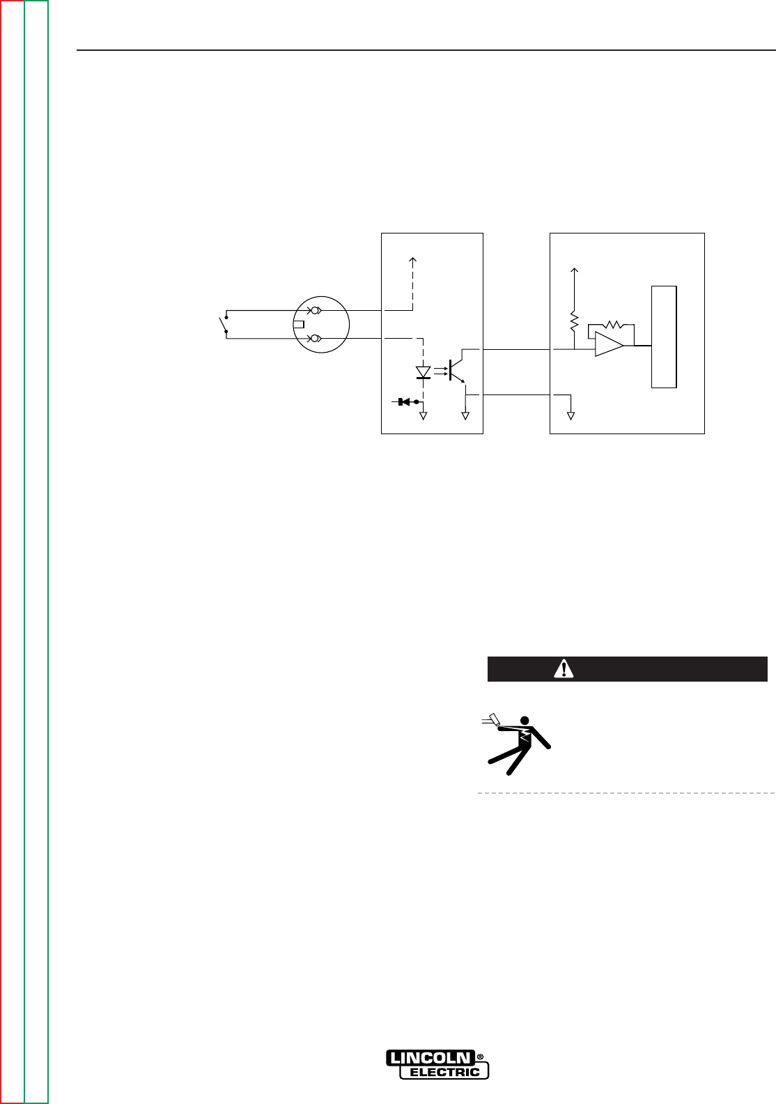
FIGURE F.9 – SIMPLIFIED TRIGGER CIRCUIT DIAGRAM
9
1
#4
#2
1J31
2J31
+17VDC
3J32
#344
TORCH
RECEPTACLE
11J3
+15VDC
TRIGGER SWITCH
IN TORCH HANDLE
OUTPUT BOARD CONTROL BOARD
P
R
O
C
E
S
S
O
R
SIMPLIFIED TRIGGER CIRCUIT
#312
12J3
COM COMAUX
D25
14J32
PROCEDURE
1. Remove input power to the PRO-CUT 80
machine.
2. Perform the Input Filter Capacitor
Discharge Procedure detailed earlier in this
section.
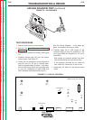
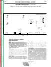
3. Locate the torch cable receptacle and leads
#2 and #4. See Figure F.9, the Simplified
Trigger Circuit Diagram. These leads are best
accessed at plug J31 on the output board.
See Figure F.10.
4. Using the ohmmeter, check for continuity
(less than one ohm) from lead #2 to lead #4.
The torch trigger must be pulled and all input
power removed from the machine. If conti-
nuity (less than one ohm) is not read, check
the leads from plug J31 to the torch cable
receptacle. Perform the Torch Continuity
and Solenoid Test.
5. If less than one ohm is read (only when the
torch trigger is pulled), proceed to the next
step. Also see Output Board LED
Definitions and related figures.
6. Apply the correct input power to the PRO-
CUT 80. Carefully check for approximately
17 VDC from plug J31 pin-1(lead#4) (positive)
to plug J31 pin-2 (lead#2) (negative). See
Figure F.10. If the correct voltage is not pre-
sent, perform the Low Voltage Circuit Test.
Also see Output Board LED Definitions and
related figures.
7. If the correct voltage is present in Step 6,
carefully check for the presence of approxi-
mately 15 VDC from plug J32 pin-3
(lead#354) (positive) to plug J32 pin-14
(lead#312) (negative). See Figure F.10. Also
see Control Board LED Definitions and
related figures. If the correct voltage is not
present, perform the Low Voltage Circuit
Test.
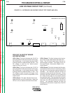
8. If the correct voltage is present in the above
test, carefully pull the torch trigger.
PILOT ARC, CUTTING ARC, AND HIGH VOLT-
AGE MAY BE PRESENT AT THE
TORCH HEAD. Perform this test
with the air input removed to avoid
a pilot arc at the torch.
WARNING