


TROUBLESHOOTING & REPAIR
F-52 F-52
PRO-CUT 80
Return to Section TOC Return to Section TOC Return to Section TOC Return to Section TOC
Return to Master TOC Return to Master TOC Return to Master TOC Return to Master TOC
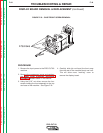
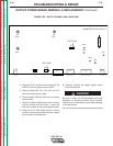
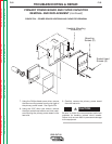
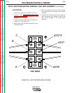
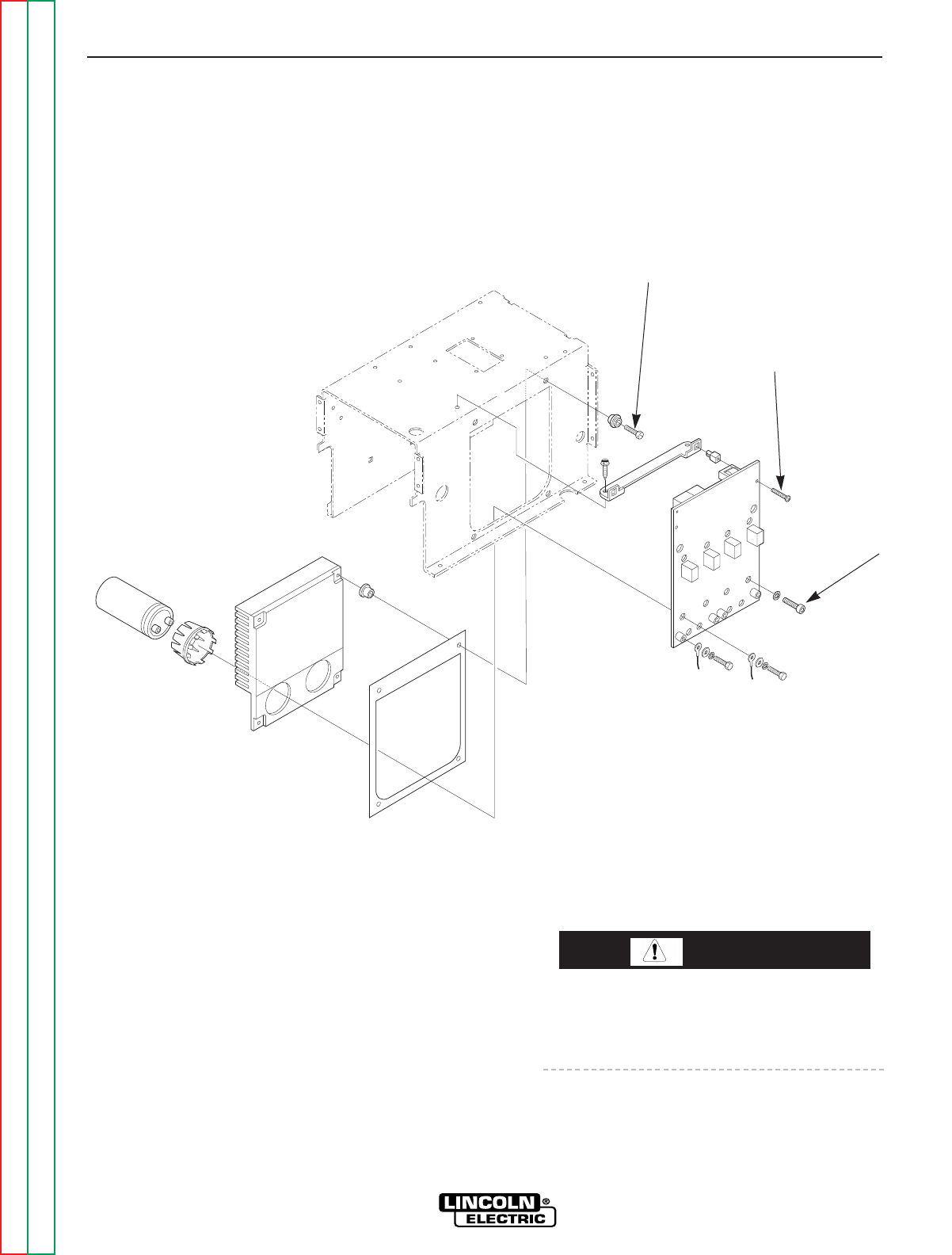
FIGURE F.24 – POWER BOARD HEATSINK AND CAPACITOR REMOVAL
PRIMARY POWER BOARD AND FILTER CAPACITOR
REMOVAL AND REPLACEMENT (continued)
7. Using the Phillips Head screw driver, remove
the two mounting screws from the top right of
the primary power board. See Figure F.24.
8. Using the 3/16” allen type wrench, remove
the eight socket head screws and lock wash-
ers mounting the primary power board to the
heat sink.
9. Carefully remove the primary power board
from the heat sink.
Be sure to follow the recommended static-free
methods for handling printed circuit boards.
Failure to do so can result in permanent damage
to the equipment.
CAUTION
Heatsink Mounting
Screws (4)
Mounting
Screws (2)
Socket Head
Screws (8)